- Ask a related questionWhat is a related question?A related question is a question created from another question. When the related question is created, it will be automatically linked to the original question.
This thread has been locked.
If you have a related question, please click the "Ask a related question" button in the top right corner. The newly created question will be automatically linked to this question.
Hi,
I thought below is the 2DFFT output with FFT shift by 4TX & 2 empty band DDMA.
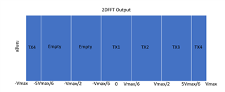
Then what's the data format on memory which is output from HWA after 2DFFT? Is it without fft shift like below?
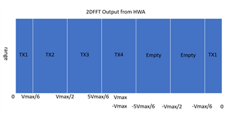
Thanks,
Chris
Hi Chris,
You can refer to the following diagram to understand the format of Doppler FFT samples stored on the memory.
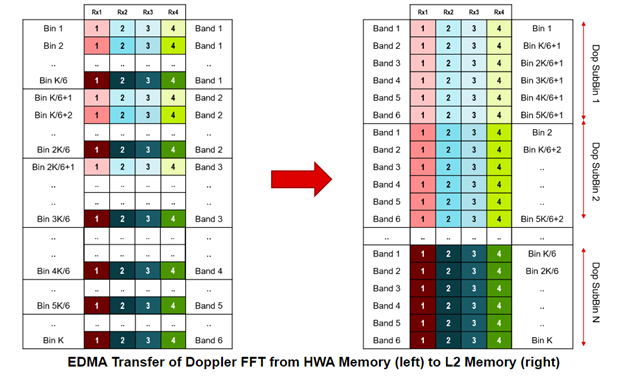
For more information, you can refer to mmwave_mcuplus_sdk_<ver>/mmwave_mcuplus_sdk_04_<ver>/ti/datapath/dpu/dopplerprocDDMA/docs/doxygen/html/index.html
Regards,
Samhitha
Samhitha,
The 2DFFT data on above picture you shared is not as our expected. We though there should be half band at beginning. Did the HWA do some shift when output the 2DFFT result to memory?
Thanks,
Chris
Hi Chris,
Data format depends on the phase shift per each Tx antenna. Can you check the phase shift that you configured?
Regards,
Samhitha
Data format depends on the phase shift per each Tx antenna. Can you check the phase shift that you configured?
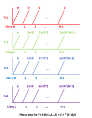
This is the config. How the 2DFFT output from HWA on memory?
What’s the output of HWA FFT looks like? Does it like FFT in matlab or fftshift in matlab? I want to know if there is shift after FFT by HWA or not. I didn't find fftshift info in TRM HWA FFT section.
Thanks,
Chris
Hi Chris,
What’s the output of HWA FFT looks like? Does it like FFT in matlab or fftshift in matlab?
HWA does not perform FFT shift. And when the 2D FFT output is transferred from HWA memory bank to L2, the format will be like the one that I shared previously.
Regards,
Samhitha
Hi Samhitha:
I have a follow-up question based on what you and chris discussed.
we use 4 Txs and 2 empty band,and we use 768 chirps,so each band has 128 points.The phase of each transmitting antenna is shown in the figure below:
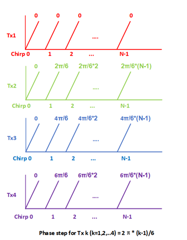
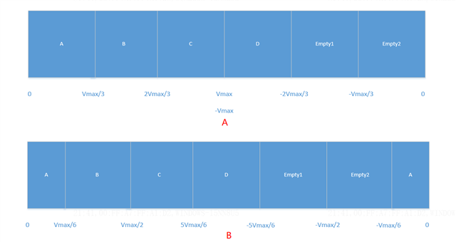
After 2D-FFT,which of the following X-coordinate arrangements is correct(A or B,why?)?We are very confused about this.
Hi Gmsy,
It should be like A. I will recheck and let you know in a day or two.
Regards,
Samhitha
Hi Samhitha,
Thank you very much and look forward to your answer.
Regards,
Bryant
Hi Gmsy,
As per my understanding, band A will not be split into two halves. Look at the subplot 2 (Doppler FFT) in the following screenshot.
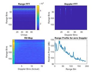
4 peaks corresponding to zero doppler are visible. And the band is not split into two halves.
Regards,
Samhitha
Hi Samhitha,
if we config the phase of TX1 is a negative phase,will there be the phenomenon of B diagram I mentioned above.

Regards,
Bryant
Hi Gmsy,
I will check and get back to you by Monday. May I know the reason why you want to achieve half bands? Can you also specify phase of other tx antennas?
Regards,
Samhitha
Hi Samhitha,
The phase of the transmitting antenna is -pi/6 pi/6 3pi/6 5pi/6.Asking this question is purely theoretical,at the same time, we have doubts about the HTML information provided by TI.As shown in the following picture:
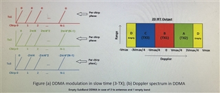
Access path file:///C:/ti/mmwave_mcuplus_sdk_04_02_00_03/ti/datapath/dpc/objectdetection/objdethwaDDMA/docs/doxygen/html/index.html.
Regards,
Bryant
Hi Bryant,
The phase of the transmitting antenna is -pi/6 pi/6 3pi/6 5pi/6.
Thank you for the confirmation. I will let you know on Monday.
Regards,
Samhitha
Hi Bryant,
The phase of the transmitting antenna is -pi/6 pi/6 3pi/6 5pi/6.
For the above-mentioned phase shift, the band is split into two halves. You can observe it in the following plot.
Regards,
Samhitha