This thread has been locked.

If you have a related question, please click the "Ask a related question" button in the top right corner. The newly created question will be automatically linked to this question.

AWR2243: 20 GHz LO signal

Part Number: AWR2243
Other Parts Discussed in Thread: DCA1000EVM, , TIDA-020047

Hello,

we are trying to set awr2243 chip on dca1000evm board to master mode and we want to enable the FMCW_SYNCOUT and FMCW_CLKOUT pins to read the 20 GHz LO signal. 

We are using mmwavelink to control the device and to set it to master mode we changed the parameter "cascading" in the mmwaveconfig.txt file from 0 to 1. However we are not able to read the signal.

Are we missing something? Or is there something else that we should try?

Thank you 

  • For Master device:FMCW_SYNCOUT needs to connect back to FMSW_SYNCIN line of same master device. Could you confirm this with your hardware connection?

  • We understand that the loopback is needed to achieve phase matched, but at the moment we would like to just feed the LO signal to a slave radar and we are not able to do it. Without the loopback are we not supposed to capture the LO signal?

  • Hello Camidz,

    Please refer to this document:

    Imaging Radar Using Cascaded mmWave Sensor Reference Design (Rev. A) (ti.com)

    Quoting the document section 2.3.3 'By using the dual LO outputs and LO inputs provided on each AWR2243 device, all devices including the master device, receive the same master device generated LO output.'

  • Hello James, 

    I still have some questions on the topic:

    - are the two outputs FMCW_CLKOUT and FMCW_SYNCOUT work exactly the same?

    - and if we only have one slave device, do you know why the system works only if we use just one port and a splitter to have the signal going both to the slave and on the loopback for the master?

    I have an additional question on awr2243 slave mode: when we read the data from the slave device there are a lot of samples that are just noise (no signal in them). We noticed that changing the sample rate and the chirp slope, the number of samples, having this problem, changes. Can you give some explanation about it, please?

    Thank you

    Camilla

  • Hi Camilla,

    I do apologize for the delayed reply.   You are correct that they work the same way. 

    You need to loopback to the master to account for delay to get the master and the slave exactly in sync.   

    the chirp characteristics have a big impact on, for example, range and velocity resolution.  This may be one reason why you see different results based on how you configure your chirps.  Let me know if you need some more specific explanation. 

    Regards,

    James

  • Hi,

    thank you for the answer.

    We tried to use the loopback on the master device by changing the pinout according to the Radar Interface Control document, but it ends up always using the internal loopback. How should we enable the master to use the external loopback?

    Regards,

    Camilla 

  • Hello Camilla,

    could you refer to this document for more in-depth explanation of how to use the loopedback LO

    AWR2243 Cascade (Rev. B) (ti.com)

    Regards,

    James

  • Thank you, we went through this documentation and it was very helpful.

    But what I wanted to ask is which parameters should we modify in the mmwaveconfig.txt file and in the c code (from the dfp examples) in order to have the device working in master or slave mode? 

    Regards,

    Camilla

  • Hello Camilla,

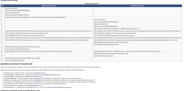
    could you check this document: mmWave-Radar-Interface-Control.pdf (can be found with a google search).  See section 5.2.1 for parameter  AWR_CHAN_CONF_SET_SB.  Please ensure that CASCADING_ CFG and  INTLO_MASTER_EN are correct.

    I'm following up with our cascade expert, but in the meantime you can also reference this

    Regards,

    James

  • Hi Camilla,

    MCU Plus SDK provides test application for 2xAWR2243+AM273x (TIDA-020047), that would be good reference for you. This example is 

    mmwave_mcuplus_sdk_04_06_00_01/mmwave_mcuplus_sdk_04_06_00_01/ti/utils/test/cascade/am273x

    Install that SDK from here https://www.ti.com/tool/MMWAVE-MCUPLUS-SDK

    .

    Here is some related/helpful queries/links https://e2e.ti.com/support/sensors-group/sensors/f/sensors-forum/1085094/awr2243-about-cascade-connection-of-awr2243

    https://www.ti.com/lit/ug/tiduf12/tiduf12.pdf?ts=1714564182101

    https://www.ti.com/tool/TIDA-020047

    Regards,

    Jitendra

  • Hello,

    Thank you for the reference. 

    I have another question related to the topic. We noticed that when we use the master device with external loopback and we don't provide a signal it seems like the device switches to internal loopback as we obtain the same data in the two cases. Is this correct?

    Moreover, we have different range FFT results depending on the type of loopback that we use. With internal loopback the peak is in the expected position, while when we use external loopback the peaks are scaled to a different position. It seems like the chirp slope and the bandwidth changed from what we configured. Is this something to expect or do you knwo what the problem could be? 

    Thanks,

    Regards,

    Camilla

  • Hello Camilla,

    If you are using a cascade its required to provide the looped back LO.  If the looped back LO signal is not correct for some reason, that will definitely impact the chirps, and hence the estimated distance, velocity etc.   The LO is used to generate the chirps after all.  

    Are you able see if the looped back signal is correct?  Do you see that it is at the right frequency and also of sufficient magnitude?

    Regards,

    James