This thread has been locked.

If you have a related question, please click the "Ask a related question" button in the top right corner. The newly created question will be automatically linked to this question.

TMP119: Layout recommandation for this usecase. Max temp for BGA balls

Part Number: TMP119
Other Parts Discussed in Thread: TMP117

Hi,
I need to implement a temperature sensing solution where TMP119 would be located on a needle PCB (ultra narrow) to get a quick and accurate measure.
I would like to know how to implement this.
PCB would be within a needle (kitchen like temperature sensor, PCB within needle with thermal coumpound
We need to use BGA for the "needle side, but we would like to know how to implement this.
Where is the sensing, what shall be implement
   - Exposed copper (but connected to which IO?)
   - No soldermask?
   ...
Also, the component is given for 150°C, but what is max temperature for BGA balls? Is there a risk of unsoldering due to melting point reach? What is the max temperature under permanent conditions?!
Thanks
BR


  • Hi Sebastien,

    • Use a flex PCB. This is going to be the thinnest PCB, which helps fit inside 'needle' and reduces thermal mass for better response.
    • Flex PCB design doesn't really like copper pour/fill, and we don't need the added thermal mass, either. 
    • I would still use masking as normal. There's no need to expose copper for thermal reasons, because this solution is enclosed in the metal 'needle.' There should not be another heat source inside the needle, and the needle's mass should overwhelm ours.
    • Flex PCB lends itself to long leads and connector of your choice outside the needle. Try to avoid routing SCL/SDA adjacent to each other for cross coupling, but even if you must, the distance is likely short.
    • Don't forget to include a bypass capacitor next to the sensor. The pull-up resistors for the bus can be populated outside the needle.

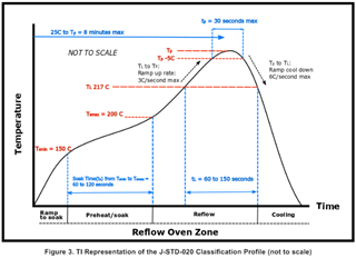
    TMP119's MSL rating is Level-1-260C-UNLIM. 260C is the peak temp recommended for solder reflow. The reflow profile is described in https://www.ti.com/lit/spraby1 where 217C is stated as the typical Liquidous Temperature.

    thanks,

    ren

  • Hi, thanks for this answer.

    I will need to dig in for Flex PCB, since the needle can be quite long (15cm), and inserting the flex within can reveal challenging...
    Also, i need to consider EMS difficulties.
    For SDA ans SCL, I would use coplanar "ground" return.

    For my qestion about BGA max temp, it was more an aging issue. It was not about soldering.
    I understand IC (semiconductor and package) have 150C operating temperature, but I was wondering about PCB or Flex and soldering...
    Solder do not like large temperaure during long time... Ok during Relflw process, for minutes, but what if temperature reaches 140°C for hours?

    What kind of solder are BGA balls? Is that non collapsing balls?
    Would you recommand SMD or NSMD process ?

  • The devices are tested and qualified for use at 150C. The qualification summary https://www.ti.com/qualificationsummary/qualsumm/home?actionId=2800 details the relevant tests and JEDEC standards.

    Please refer to the app note AN-1112 https://www.ti.com/lit/snva009 for information on SMD/NSMD.

    The ball material should be listed in the datasheet, but it is not yet populated for TMP119. I expect it to be the same as TMP117, also shown here.

    I'm not familiar with collapsing solder balls, but a TIer previously stated on E2E that it is dependent on the PCB layout, not the ball construction. 

    e2e.ti.com/.../how-do-we-know-bga-is-collapsing-or-noncollapsing-bga-balls

    thanks,

    ren