This thread has been locked.

If you have a related question, please click the "Ask a related question" button in the top right corner. The newly created question will be automatically linked to this question.

AWR2944EVM: Is it possible to develop and test another algorithm using the AWR2944 row data ?

Part Number: AWR2944EVM
Other Parts Discussed in Thread: AWR2944, UNIFLASH

Hi expert, 

1. Is it possible to edit the provided DSP algorithm or write another algorithm using the same row data used by the provided one and compare the performance between them? 


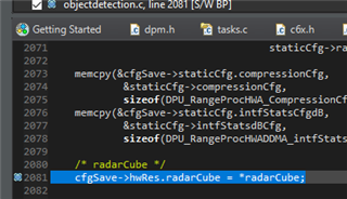
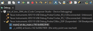
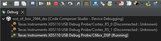
2. Is it possible to debug the provided DSP code and read variable data and memory data? 


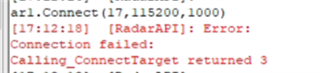
3. How do I use the DCA1000 to read the captured row data from AWR2944 and use it in MATLAB? 


4. Is this row data for all virtual Rx ((12 in the first row) and (4 in the second)) or modulated row data for the 4 Rx and needed to be demodulated to (12 v-Rx and 4-v-Rx)??  

Please kindly share your experience on how to develop and test another algorithm using the AWR2944 row data.

Thank you,
M.Yehia
  • Hi M.Yehia, 

    1. You can save the adc data in CCS or via a data capture card(DCA1000). Once your adc/raw data is saved you can set a breakpoint in your code at the correct location and load the corresponding data in CCS. 

    2. Yes, you can set a breakpoint in CCS and read these values under expressions

    3. Once you capture the raw data in DCA1000 it is stored in a binary file on your pc. You can load that file to MATLAB

  • 4. Please see section 25 of mmwave_studio_user_guide.pdf found in C:\ti\mmwave_studio_03_01_01_00\docs, it outlines the Format of the raw captured file

  • Regarding 1&2,  here is what I tried. After running, in debugging mode, I pressed resume to jump to the breakpoint. However, the code jumped to the idle task, I think there is no configuration of any mode (TDM or DDM) has been sent. 


    So could please tell me how to send configuration in debugging mode to jump to radarCube to read the raw data ?
    Moreover, I want to know which function is called to read the raw data in out_of_box_2944_dss so I can put a breakpoint at the right place ?

    3- I tried to use DCA1000, but this problem happened  
    I followed https://e2e.ti.com/support/sensors-group/sensors/f/sensors-forum/1232497/awr2944-awr2944-hecr-based-on-sdk4-4-how-to-capture-adc-raw-data-via-dca1000   
    ,and the solution is not clear, I tried everything but nothing change.

  • Hi Mohamed, 

    You can pass the configuration using a software like tera term. Before you set up breakpoints I advise you run the demo as is with the configuration to make sure it is working. 

    Can you share what sdk and what demo in that sdk you are trying to run?

    For the DCA1000 problem I advise you start another e2e thread for better resolution. Please mention all your steps you have undertaken so far as well as where/how you run into this problem.

    Thankyou!

  • The sdk mmwave_mcuplus_sdk_04_04_01_02 and the demo "out_of_box_2944_dss & out_of_box_2944_mss"
    1. Are there any steps to send the configuration using the Tera term?
    2. How can we run with configuration and check that the demo worked using the CCS?" The only way I tried and worked was that: 
         - Flashing; SBL Image: sbl_qspi.release.tiimage; and App Image: out_of_box_2944.appimage  using UniFlash
         - I used https://dev.ti.com/gallery/view/mmwave/mmWave_Demo_Visualizer/ver/4.4.0/ to send the DDM configuration and display the figures, which means it worked.

    - To debug, I flashed SBL Image: sbl_qspi.debug.tiimage and App Image: out_of_box_2944.appimage, then used CCS.
    So how do I verify the demo is working using CCS? and send configuration in debug mode?

  • 1.Tera term is an alternate way to pass configuration, mmWave Demo Visualizer should be sufficient for your purposes. For tera term you connect the serial port, configure the baud rate, and set up a small transmit delay. You can paste the configuration into the terminal to pass it to the device 

    2.To run the demo with CCS, flash the evm with the ccs debug app image given under C:\ti\mmwave_mcuplus_sdk_04_04_01_02\mmwave_mcuplus_sdk_04_04_01_02\ti\utils\ccsdebug. Put the device in functional mode, reconnect to pc, launch target configuration, connect to the core, reset the memory, load the .out file and run. You can use the ti mmWave Demo Visualizer to pass the cfg