This thread has been locked.

If you have a related question, please click the "Ask a related question" button in the top right corner. The newly created question will be automatically linked to this question.

IWRL6432BOOST:

Part Number: IWRL6432BOOST
Other Parts Discussed in Thread: IWRL6432, SYSCONFIG, UNIFLASH,

Tool/software:

Based on my last question - about reading information from TLVs on a Rapsberry pi:


Hi everyone,

I've been doing some digging:

Question 1)
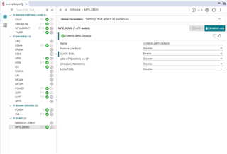
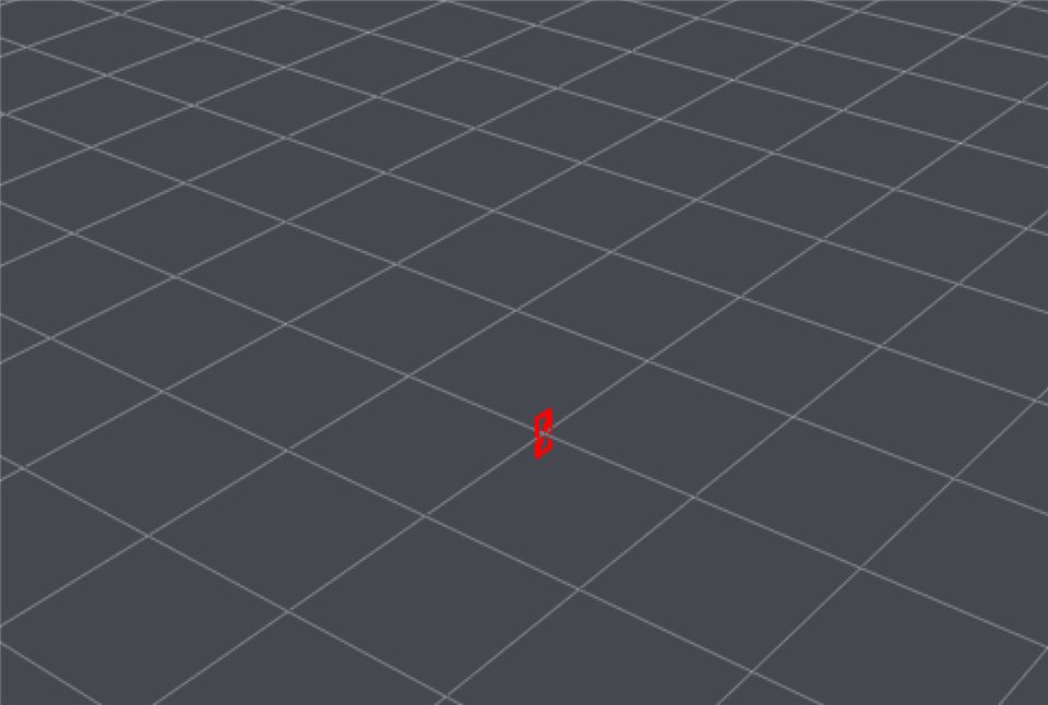
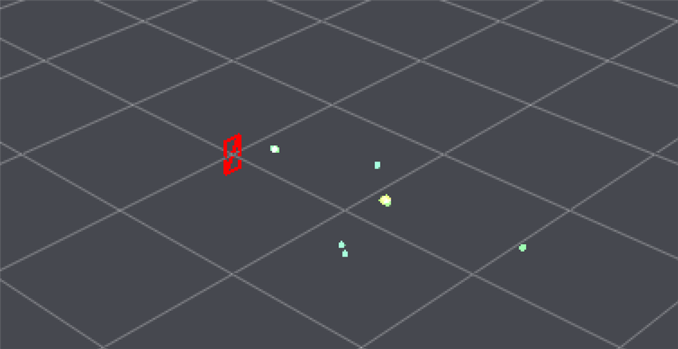
If you want to use a raspberry Pi to connect to IWRL6432 boost, and read the data and print Detected Objects, then you need to use a parser such as the ones in the Radar Toolbox e.g. tlvParser.py.

Python files like main_gui.py - do NOT contain the parser (no reference to detected objects in that python file).

Question 2)
This is all in the Radar Toolbox section - there are no Python files in the SDK - correct?

  • Hello, 

    Your understanding is correct. For examples of parsing output data from the device, refer to the python visualizer files in the Radar Toolbox. The files are located at {RADAR_TOOLBOX_INSTALL}\tools\visualizers\Applications_Visualizer\common. tlv_defines.py, parseTLVs.py and parseFrame.py will be the most relevant. 

    Regarding Q2, Yes, this is all referring to the Radar Toolbox. The source code for the visualizer in the SDK is not provided. 

    Best Regards,

    Josh

  • Hi Josh thanks.

    Question 3)

    Do you need to configure the IWRL6432BOOST every time? 

    E.g. with SDK visualiser step 1 - Send config to device Step 2 - see results.

    But could you do step -1 on a windows laptop. Then plug the IWRL into a raspberry pi and start parsing straight away?


    I'm asking this because if you just need to run the parser on the raspberry pi - it should be okay with the OS "Rasbpian"
    Other wise I'd need Ubuntu 24 LTS.

    Thanks,
    Fred

  • Hi Fred, 

    But could you do step -1 on a windows laptop. Then plug the IWRL into a raspberry pi and start parsing straight away?

    The issue here would be that the device resets when you disconnect and reconnect power so it would again require sending the configuration. 

    Yes, the device needs to be configured every time it resets; however, it is possible to 'hardcode' the configuration within the demo code so that the device will automatically configure and start itself upon receiving power. This may be helpful in your case if you do not wish to send the configuration commands from the raspberry pi to the IWRL6432. 


    For SDK 5.4.0.1, the easiest way to do hardcoded configuration (HCC) is using the QUICK_EVAL feature. To enable HCC, you can enable the QUICK EVAL setting in sysconfig for the example project. 

    Then in mmw_cli.c, you can list each of the configuration commands in radarCmdString (or radarCmdStringAOP if AOP device is used). Note, you may need to update MAX_RADAR_CMD to match the number of commands in your configuration. After this you can rebuild the example project and reflash the board with the updated appimage. If your configuration is valid then the sensor will begin chirping and outputting data once it receives power without the need to configure over UART. 

    Best Regards,

    Josh

  • Okay thanks.

    And the less techy, backup options is:

    I get Radar Toolbox on Ubuntu 24 Raspberry pi, then I write a python code which first configures the board and waits for it to be done.

    Then parses the data. Correct?

    And in radartool box folder are there any python files that automatically send a config file to the device?

  • Fred,

    Yes, configuring the sensor from the raspberry pi over UART connection would also be possible.

    And in radartool box folder are there any python files that automatically send a config file to the device?

    You can again refer to python code in the radar toolbox to see how we do this in the visualizer but there is not a standalone python script which does just the configuration of the sensor so you will need to extract the code which is useful to you. For configuring the device, the relevant code can be found at  {RADAR_TOOLBOX_INSTALL_DIR}/tools/visualizers/Applications_Visualizer/common/gui_parser.py (see the functions connectComPort and sendCfg). 

    Best Regards,

    Josh

  • I've been on CSS - I've Imported the MPD demo into CSS and then opened sysconfig and enabled QUICK_EVAL.
    In the mmwave_cli.c file I see the config characters already populated so thats good.

    Now I'm trying to generate an .appimage, this isn't mentioned anywhere though. Can you let me know?

    I've built the file in CSS but can't find any appimages. I do see in the SDK folder I have on my C:/ that the respective mmw_demo folder does have appimages though. 


    And is there anyway to check the hardconfig flash worked - like in the radar toolbox example 

    dev.ti.com/.../node


  • Hey, could you let me know how to make the .appimage please? I've built it in CSS but cant find the .appimage


  • Hi Fred, 

    If you have built the demo in CCS you should be able to find the .appimage at in the project directory in your CCS workspace. This will depend on where you have specified your CCS workspace but by default it should be located at:  C:/Users/{USER}/{CCS WORKSPACE}/{PROJECT}/{BUILD CONFIGURATION}

    The build configuration will either be 'Release' or 'Debug' So look for a folder with one of those names in your project folder. You should find the .appimage file within. 

    In the mmwave_cli.c file I see the config characters already populated so thats good.

    I also just wanted to give you a heads up that the default configuration in these structures is specific to this quick eval feature. It is a very simple configuration and I believe it is very limited on the maximum range and in terms of what outputs it enables. For a more standard configuration, you can copy the commands from one of the .cfg files provided at: {MMWAVE_SDK5_INSTALL_DIR}/examples/mmw_demo/motion_and_presence_detection/profiles. 

    Best Regards,

    Josh

  • Thanks Josh,

    Just FYI - I've tried building and I've got a really weird bug going on.

    My board is a IWRL6432 -

    When I import the two projects in mmwave_demo ->  wrlx14xx   and    wrlx64xx       the first one builds fine and I can see the .appimage.

    The second one doesnt build and this is the error I get:

    [120]makefile_ccs_bootimage_gen:64: recipe for target 'all' failed
    [121]makefile:184: recipe for target 'post-build' failed
    [122]process_begin: CreateProcess(NULL, C:/ti/MMWAVE_L_SDK_05_04_00_01/tools/auth_tool/Integrity_generator.exe C:/ti/MMWAVE_L_SDK_05_04_00_01/tools/auth_tool/encsymm.txt C:/ti/MMWAVE_L_SDK_05_04_00_01/tools/auth_tool/encsalt.txt C:/ti/MMWAVE_L_SDK_05_04_00_01/tools/auth_tool/encinfo.txt motion_and_presence_detection_demo_integrity.bin app motion_and_presence_detection_demo.Debug_rprc.bin rfs C:/ti/MMWAVE_L_SDK_05_04_00_01/firmware/mmwave_dfp/rfsfirmware/xWRL6432/mmwave_rfs_patch_rprc.bin, ...) failed.

    [123]gmake[3]: *** [all] Error 2
    [124]gmake[2]: [post-build] Error 2 (ignored)


  • Hi Fred, 

    You haven't made any changes after importing the project, right? Just building the code as is? If so, then yes this is not expected. Please give me some time to look into this. It looks like you are using SDK 5.4.0.1, Can you also let me know which version of CCS you have installed?

    Regards,

    Josh

  • Hey Josh,

    I reinstalled the SDK. Then trying again my antivirus threw up so set a flag for this .exe file. Now it works.

    I've tried flashing with the appimage and I think it works on the SDK visualilser flash. But doenst work on the uniflash (verification error).

    Should I be concerned?


    P.S - on the visualiser - the quick eval part is working.

    However, I'm not seeing any detection information such as obstacles or point cloud. Not sure if I should.

    I'm going to attempt those Python parser scripts.

  • Hey Josh,

    I've loaded up the GUI from radar tool box.

    I'm connected and receiving frames, 

    but nothing is showing: 

    -----------

    got it working, probably the GUI part of the config that I changed.

    my next step is now to try all the python files..

  • Ok, I've got all the python dependancies. When I run gui_main.py the visualiser opens.

    When I run parseTLVs.py, nothing happens.

    I think there must be a few setup processes? Like opening a com port? 

    Actually the easiest way of doing this is just going to gui_main.py, disable the GUI from opening, and just print the objects right?

    I need to hardcode the "start without sendcfg" and also COM port

  • Hi Fred, 

    I'm glad to hear you're making progress. 

    When I run parseTLVs.py, nothing happens.

    The python files provided here are expected to work in the context of the Applications Visualizer. The only file which is intended to be run as a script is gui_main.py, the other files just organize different classes/functions. 

    Actually the easiest way of doing this is just going to gui_main.py, disable the GUI from opening, and just print the objects right?

    In essence, yes, but that may be over complicating it. Pretty much everything you should really need is contained in gui_parser.py (and subsequent calls to parsing functions in other files). But that doesn't mean that you can just run gui_parser.py and it will just work right away. Again, this UARTParser class that it defines is expected to be used within the context of the GUI so you might need to make a few changes at some parts (like hardcoding the com port or automatically detecting it, etc...)

    Regards,

    Josh

  • Hey Josh,

    If I'm correct all the classes being setup in gui_parser are not actually getting called there.

    Do you know which classes I should call to get things running? I've hardcoded the comport

  • Hi Fred, 

    The UARTParser class is instantiated in gui_core, but I don't think that is necessarily relevant to you. Most of the pieces of the gui code are using pyqt in some way. Since you are only interested in parsing the output data, and not visualizing, I think the easiest path would be to just create a new python script of your own, create an instance of the UARTParser class (since you are using 6432 you should specify the parser type as 'SingleCOMPort' = UARTParser(type="SingleCOMPort"), then call connectComPort(), then call readAndParseUartSingleCOMPort(). 

    Regards,

    Josh

  • Hey Josh, 

    I've done it with the help of some chatgpt. I think its working, just gotta whack it all in a while loop.

    Okay so imagine this, Im flying a drone (horizontally about 2m off the ground). I turn the motors off but our mmwave detector is going to turn on the motors when it free falls to about 50cm off the ground.

    So initially, can easily use the detected object centroids to return the distance from object (ground) and likely use an LP filter to smooth this out and threshold it.

    Do you have any other ideas or know demos that might be relevant? The drone is travelling horizontally at about 5m/s and the time its going to drop is 600ms. 

    Would you look at any other method besides basic centroid/cluster returns?

    Perhaps velocity - how would I call the parsevelocityTLV?


  • Fred, 

    I think you should look at our High Accuracy Range Detection Demo. They typical use case is actually sensing the fluid level of a large tank with high accuracy but I think it could be useful for you here also for altitude sensing.

    Perhaps velocity - how would I call the parsevelocityTLV?

    This TLV is specific to one of our demos and not universally available. It comes from the True Ground Speed Demo, which may also be interesting for you but the intended purpose is to calculate the true ground speed travelling horizontally which I believe is not what you are looking for. However, I will point out that the each detected point (output in the point cloud TLV) has an associated velocity so you might try averaging the velocities of the detected points. 

    Best Regards,

    Josh

  • Thanks.

    I've got point clouds and some cluster centroids printing with scikit learn.

    I have a hunch that the output is different somehow than what I see with the SDK visualiser.

    Is there any difference between outputs from the mmwave SDK vs teh radar toolbox scripts? Or it should output the same data?

  • Hey Josh,

    Been playing with the results of this demo and its good.

    One problem - doing the QUICK_EVAL enable doesnt work this time. In fact it looks like it disables the demo completely even if you do "start with config" in radar Industrial Visualiser.

    I tried flashing with QUICK_EVAL enabled with and without the correct cfg inside mmw_cli.c and both times I get a port error.

    Is it just because im running the exe? or is there another way to hardcode for this demo?

    Thanks

  • Hi Fred, 

    Do you have the 'baudRate' command included in the hardcoded parameters in mmw_cli.c? If so, this may be causing an issue. Typically, when that command is sent to the device, the visualizer will see it an update the baud rate used for the serial connection but since the visualizer does not see the configuration in the case of HCC, then it does not know to use the updated baud rate.

    Best Regards,

    Josh

  • There is a baudrate section but it doesnt include an actual baudrate. It also has this same code in the example project which worked.

    I've got it working by parsing the cfg using python, but I have to plug it out and in each time I run the code. Should I do a sensor stop or flush or something at the beginning of the code?

    Another question - Is there anyway to increases peaks detected by more than just the 3? the numpoints on the outputDict is 3, but would be useful to gather more and just take the furthest away from the sensor as the ground. E.g. Capture even weaker reflections as they penetrate thru crops.

    And P.S - if I just need the USB, antenna and the chip, do you have any reference designs or suppliers who have made a basic PCB like that?

    PPS - I've been noticiing this behaviour today - it keeps detecting a peak at about 0.087 - 0.09 m. Maybe its detecting itself? It didnt use to do that.


    Thanks
    Fred

  • Hi Fred, 

    There is a baudrate section but it doesnt include an actual baudrate. It also has this same code in the example project which worked.

    I'm not sure what you mean here. Can you please clarify? It seems maybe you're able to progress beyond this but for clarity and for anyone who might come across this later I will try to better explain my meaning. 

    When QUICK_EVAL is enabled (for hard coded configuration), and the configuration parameters are included in radarCmdString (mmw_cli.c), you should ensure that "baudRate 1250000 \r\n" is NOT present in the configuration. If you remove that line, the baud rate will remain as what is configured in the UART tab of sysconfig (by default that is 115200). This may be fine if the configured frame time is long enough to still output the data at the slower baud rate; however, it may be the case that the data transfer is too slow and the demo will crash. To avoid this, I would recommend updating the default baudrate to 1250000. You would need to change this in the uart tab of sysconfig and also in the python code which opens the serial connection.

    I've got it working by parsing the cfg using python, but I have to plug it out and in each time I run the code. Should I do a sensor stop or flush or something at the beginning of the code?

    Can you clarify what you mean here? Are you still using hard coded config? When you say "run the code" I suppose you mean the python program, correct? 

    For the additional questions please create a new post/s.

    Best Regards,

    Josh

  • So for baudate,

    within mmw_cli.c there is no cfg item that states Baudrate = xyz.

    However there is this define in the code:

    #if (FEATURE_LITE_BUILD_EN == 0)
    //Enable this define, to allow dynamic swith to 1.25Mbps baud rate, then execute CLI cmd: baudRate 1250000
    #define ENABLE_UART_HIGH_BAUD_RATE_DYNAMIC_CFG
    

    And i've just checked my sysconfg - it was set at 115200.

    So according to this - there should be a discrepancy and hence the crash?

    The only baudrate I see is in gui_parser and it says
        def sendLine(self, line):
            if(self.cliCom.baudrate == 1250000):
                for char in [*line]:


    So I think this might have been where the discrepancy was happening. I'll edit sysconfig and try.


    For the unplug question - yes Im running on python code. I'm reading and parsing the cfg and then running detected points well.

    But if I Ctrl+C the program on python terminal, I cant just restart it. I've got to unplug it and plug it in.

    So I'm guessing theres some sort of closing loop that needs to be done.


  • Hi Fred, 

    My sincere apologies for the delay. The front end needs to be reset each time you want to send a new configuration. The IWRL6432BOOST board has the XDS110 which you can issue a simple reset command which will also reset the IWRL6432. Please check section 3.7.3.1 of the XDS110 User Guide. https://www.ti.com/lit/sprui94 

    Best Regards,

    Josh

  • Hey Josh,

    No problem.

    I've been porting my code from Windows to Linux for the raspberry pi.

    Do I need the SDK installed to run a version of gui_parser.py?

    The config im sending actually points to a file in the SDK folder:
    "adcDataSource 0 C:/ti/mmwave_lp_sdk/examples/datapath/common/testBench/major_motion/adc_data_0001_CtestAdc6Ant.bin\n' "

    Could I just copy that file and I'd be okay?

    Thanks

  • Answer: 

    No - I dont have SDK, Toolbox and I dont have that file that the config is pointing to either.

    I needed to edit the config.txt and cmdline.txt on boot of Rpi to enable UART (lots of links show how to do this).

    I had to reset the USB connection a few times on linux to make sure it worked, but it worked! :o exciting stuff.

  • Hi Fred, 

    Sounds like you're making good progress. I think you might have answered your own question already but there shouldn't be any dependencies on the python visualizer code besides the specific python version and python module version mentioned in the Application's Visualizer user guide. That command in the cfg files is only used for testing purposes you should be able to remove it. 

    Best Regards,

    Josh

  • Hey Josh,

    Hope all is well.

    I've been trying to get this going faster - frameCfg set to " 1 0 200 1 50 0 "  should be twice the default rate - but its still a bit slow and giving me packet warnings.

     Is it possible to get it much faster?

    Thanks
    Fred

  • Hi Fred, 

    So just to confirm, do you mean that after changing the frame period from 100ms to 50ms you do not see the expected rate increase? Is this seen with the host as raspberry pi or PC or both? 

    If you do see the expected rate increase and are still looking to further increase the speed I would say you will start to run into issues as you continue to decrease the frame period. Each frame can be thought of consisting of these blocks: chirping, processing, transmitting output data and finally idle (or deep sleep if low power modes are enabled). The chirping time is going to be the same each frame which is of course determined by the configuration. The processing time depends on which processing blocks are enabled (DPUs) but can also vary slightly frame to frame depending on the scene (more detections means longer processing time). Similarly the data output size and therefore time depends on what data outputs are enabled (controlled by the guiMonitor CLI command) but can also vary frame to frame (again more detections means more data to output). The frame period which is configured in frameCfg must be greater than the sum of all of these or else the code will crash. 

    Can you expand on the packet warnings a bit? Are you noticing missing data? What uart speed are you using? Also if you are seeing this on the raspberry pi I would suggest confirming the max uart speed supported by your raspberry pi. 

    Regards,

    Josh

  • Hey Josh,

    Sorry for the delay.

    In the end I had a time.sleep() which was pretty high.

    I also had a look at the RPI UART default - its stuck at 115200. In order to get it up to 1250000 I needed to edit the CMD line - its a quick fix and plenty of other posts have the instructions but I think that helped.

    So now its going fast and Im not getting those packet warnings.


    So last major problem I've got -> When I start my python script, I'm parsing the config file. Generally, this fails about 5-6 times before the config is succesfully parsed.

    After it is parsed I can actually Ctrl+C my script, and at any time if I run it again, it doesnt parse the config and just starts running e.g. printing the radar data which is great.

    So my question is, why does the parsing of config fail so much initially. Like I'd like to make this thing run on startup but It cant, I have to Ctrl+C many times and keep retrying.

    I made sure the Baudrate on the code composer and app-image is 1250000, so I dont think its that. It might be in the cfg parsing command Ive got?

    Do you have any ideas?

    Thanks
    Fred

    class Core:    
        def __init__(self):
            self.frameTime = 50
            self.parser = UARTParser(type="SingleCOMPort")
            self.serial_port = serial.Serial('/dev/ttyACM0', 115200)  # Update with the correct serial port for Teensy 4.1
    
        def parseCfg(self, fname):
            log.info(f"Parsing configuration file: {fname}")
            with open(fname, "r") as cfg_file:
                self.cfg = cfg_file.readlines()
            for line in self.cfg:
                args = line.split()
                if len(args) > 0:
                    if args[0] == "frameCfg":
                        if len(args) < 4:
                            log.error("frameCfg had fewer arguments than expected")
                        else:
                            self.frameTime = float(args[5]) / 2
    
        def sendCfg(self):
            try:
                self.parser.sendCfg(self.cfg)
                sys.stdout.flush()
            except Exception as e:
                log.error(e)
                log.error("Parsing .cfg file failed. Did you select the right file?")

  • Hi Fred, 

    Can you share any more details on the parsing failure? Do you mean the python code is failing or the code running on the device? I think the former but please confirm. 

    Regards,

    Josh

  • Hey Josh,

    Sorry for the delay. I actually made a video to show what is going on.

    So, first attempt - the CFG parsing is almost working. Then it finishes and I get empty b'' characters. When this happens I have to unplug the IWLR6432 and plug it in again.

    More attempts.

    Generally If I dont get the right characters in teh beginning I CTLR+C out of it until I get them.

    Then I get them and you can see it works (at the end).

    So it does work, but it just requires alot of CTRL+C and re-plugging,

    Do you think theres a conflict of code or something? OR the CFG looks wrong?
    Cfg attached:

    % ***************************************************************
    % LevelSensing:  Chirp configuration and Processing chain are 
    % designed for high accuracy level sensing.
    % ***************************************************************
    channelCfg 1 1 0
    chirpComnCfg 8 0 0 512 1 45 0
    chirpTimingCfg 6 23 0 75 58
    frameCfg 1 0 200 1 50 0
    guiMonitor 2 1 0 0 0 0 0 0 0 0 0
    zoomCfg 16384 1 3
    sigProcChainCfg 32 2 1 0 4 4 0 15 
    cfarCfg 2 8 4 3 0 12.0 0 0.5 0 1 1 1
    aoaFovCfg -60 60 -40 40
    rangeSelCfg 0.0 10.0
    clutterRemoval 0
    compRangeBiasAndRxChanPhase 0.0 1.00000 0.00000 -1.00000 0.00000 1.00000 0.00000 -1.00000 0.00000 1.00000 0.00000 -1.00000 0.00000
    adcDataSource 0 C:/ti/mmwave_lp_sdk/examples/datapath/common/testBench/major_motion/adc_data_0001_CtestAdc6Ant.bin
    adcLogging 0
    lowPowerCfg 1
    factoryCalibCfg 1 0 40 0 0x1ff000
    baudRate 1250000
    sensorStart 0 0 0 0
    

    /cfs-file/__key/communityserver-discussions-components-files/1023/20240815134210.mp4

  • P.S - I've been timing this call in python:

    outputDict = self.parser.readAndParseUartSingleCOMPort()

    It takes 50ms, which is big. Is there anyway to make it faster?

    Kind regards,
    Fred

  • I'm able to lower the cfg to 20ms :

    channelCfg 1 1 0
    chirpComnCfg 8 0 0 512 1 45 0
    chirpTimingCfg 6 23 0 75 58
    frameCfg 1 0 200 1 20 0


    But any lower and I get a config error.

    Is it possible to get it lower? 5 or 10 instead of 20 ?

  • Hi Fred, 

    Can you please create a new post for the question about reducing the frame rate for the level sensing demo? This helps future users who might have the same question by making it easier to find. 

    I think the issue you're facing when sending the configuration is related to the python code. There doesn't seem anything wrong about the config you shared and when I test this with the prebuilt binary for the level sensing demo it runs smoothly with no crashing. Are you using the same example code for sending the configuration that is provided in the visualizer? I know that we had to include a character delay when sending the commands with a baud rate of 1250000, if you've slimmed down the python code and removed that part it may be causing issues. Below is from gui_parser.py in the toolbox. 

    Regarding the empty b'' characters, I'm not sure how much you've modified the visualizer python code at this point, I imagine quite a bit, but we have seen the empty b" characters in cases where the sensor was started and running then you try sending a new configuration without restarting the sensor. For example, you can replicate this by running an example using the Applications Visualizer, then closing the visualizer and reopening it again and trying to start the demo again without resetting the device via nReset button or disconnecting and reconnecting the USB.

    Best Regards,

    Josh

  • Hey Josh,

    Sorry for the delay. I'll paste my code here.

    I'm not touching the gui_parser.py file, I'm calling the existing method in my core though. In gui_parser this is all wrapped under UARTParser.

    These are methods called from gui_parser. 

    • sendCfg(cfg)
    • readAndParseUartSingleCOMPort()
    • parserType (attribute)

    But I notice I have a parseCfg method too which isnt within gui_parser.

    class Core:    
        def __init__(self):
            self.frameTime = 10
            self.parser = UARTParser(type="SingleCOMPort")
            self.serial_port = serial.Serial(
                '/dev/ttyACM2', 115200, timeout=1
            )  # Update with the correct serial port for Teensy 4.1
    
        def parseCfg(self, fname):
            log.info(f"Parsing configuration file: {fname}")
            with open(fname, "r") as cfg_file:
                self.cfg = cfg_file.readlines()
            
            for line in self.cfg:
                args = line.split()
                if args and args[0] == "frameCfg":
                    if len(args) < 4:
                        log.error("frameCfg had fewer arguments than expected")
                    else:
                        self.frameTime = float(args[5]) / 2
    
        def sendCfg(self):
            try:
                self.parser.sendCfg(self.cfg)
                sys.stdout.flush()
            except Exception as e:
                log.error(e)
                log.error("Parsing .cfg file failed. Did you select the right file?")
    
        def getPointCloud(self):
            ser = self.serial_port
    
            if self.parser.parserType == "SingleCOMPort":
                outputDict = self.parser.readAndParseUartSingleCOMPort()
                
                if 'pointCloud' not in outputDict or 'numDetectedPoints' not in outputDict:
                    print('No peaks found further than 0.1m.')
                    return None
    
                pointCloud = outputDict['pointCloud']
                numPoints = outputDict['numDetectedPoints']
    
                peaks = [
                    (
                        round(pointCloud[i, 1], 3),
                        round(np.log10(round((pointCloud[i, 4] * 64), 4)), 3)
                    )
                    for i in range(numPoints)
                    if round(pointCloud[i, 1], 3) > 0.1
                ]
                          
                # Log all detected ranges to a file
                with open("detected_ranges.txt", "a") as log_file:
                    for i in range(numPoints):
                        log_file.write(f"{round(pointCloud[i, 1], 3)}\n")
    
                if not peaks:
                    print('No peaks found further than 0.1m.')
                    return None
    
                highest_peak = max(peaks, key=lambda x: x[1])
                distance = highest_peak[0]
    
                # Log distance to file
                with open("distance2.txt", "a") as log_file:
                    log_file.write(f"{distance}\n")
    
                # Send distance to Teensy
                if distance is not None:
                    self.sendDistanceToTeensy(distance)
                
                return highest_peak
    

  • Hi Fred, 

    I'm sorry for the delayed response here. I can see in your core class that you create the serial port with a baudrate of 115200, however, based on our previous discussion I believe you built the appimage to use a baudrate of 1250000 by default. Is this correct?

    Also, just to rule out any issues caused by different python version or python module versions, can you confirm that your python environment exactly matches the recommendations in the Application Visualizer User Guide, in the section titled "working with the visualizer source code"?

    Best Regards,

    Josh

  • Hey Josh,

    Thats the serial for the teensy4.1- not the radar. The radar is on a different COM which is defined in Main().

    Yeah doesnt seem like any problem from the requirements.

    Im using Ubuntu 23. Cant get 18 or 16 on the Rpi. But I dont think its that.

    Fred

  • Hey Josh,

    I think it might be also a good time to retry hardcoding this config.

    I retried hard-coding and it didnt work, so I believe that hardcoding is not possible with level_sensing - can you confirm?

    If its impossible I'll continue trying to get this python to behave

  • Hey Josh, 

    Abit earlier we were talking about hardcoding the config and I said the quick_eval didnt work.

    However, I downloaded a few other examples and the quick_eval feature did work with them.

    So I looked at dependencies and installed CSS12.8 (not Theia) And SDK 5.5 and even Sysconfig 1.2.

    This got rid of all the errors and the build worked, but then I get 3 warnings: unused variables:

    "unused variable 'retVal' [-Wunused-variable] dpc.c /high_accuracy_xwrl64xx line 2323 C/C++ Problem"

    Same error for variables: "skipFrmCntr" and "trackerData".

    There may be a file missing.

    I've done alot to try to get it working and couldnt see any other posts about these errors.


    Do you think you could try hardcoding this example and see if it works? 
    If so I'd llike to give you my config which prints at 20ms. 


    Best regards
    Fred


  • Hi Fred, 

    Those warnings should not cause any issues, they are likely artifacts of an old version of the demo code and can be ignored. It seems that you're correct and there is a bug with the level sensing demo when trying to enable quick eval for hard coding the configuration. I have been able to get around the bug by commenting out these lines in mmwDemo_TransmitProcessedOutputTask of level_sensing.c.

            /*****************************************************************************************************/
            /* If Default Config: LED is blinked at frequency proportional to range of nearest detection */
    //        if(gIsDefCfgUsed == 1)
    //        {
    //            rngProfile = gMmwMssMCB.rangeProfile[1];
    //            if (gTestMinMpdCentroid != -1)
    //            {
    //                for(binIdx=1; binIdx < round(gMmwMssMCB.rangeSelCfg.max/gMmwMssMCB.rangeStep); binIdx++)
    //                {
    //                    if(binIdx == 1)
    //                    {
    //                        rngProfileMax = rngProfile[binIdx];
    //                        rangemmrnd = binIdx;
    //                    }
    //                    else if(rngProfile[binIdx] > rngProfileMax)
    //                    {
    //                        rngProfileMax = rngProfile[binIdx];
    //                        rangemmrnd = binIdx;
    //                    }
    //                }
    //
    //                gTestRangeLED = rangemmrnd * gMmwMssMCB.rangeStep;
    //
    //                if(fabsf(gTestMinMpdCentroid - gTestRangeLED) <= gMmwMssMCB.clusterParamCfg.maxDistance)
    //                {
    //                    rangemmrnd = round(rangemmrnd * gMmwMssMCB.rangeStep * 10) * 100;
    //                }
    //                else
    //                {
    //                    rangemmrnd = round(gTestMinMpdCentroid * 10) * 100;
    //                }
    //
    //                if(rangemmrndold != rangemmrnd)
    //                {
    //                    if(rangemmrnd > 100)
    //                    {
    //                        // Configure RTI Counter 0
    //                        TimerP_Params_init(&idleTimerParams);
    //                        // Selecting Osc clock as source for RTI with prescale 1.
    //                        idleTimerParams.inputPreScaler = 1;
    //                        idleTimerParams.inputClkHz     = 40000000u;
    //                        idleTimerParams.periodInUsec   = rangemmrnd * 500;
    //                        idleTimerParams.oneshotMode    = 0;
    //                        idleTimerParams.enableOverflowInt = 1;
    //                        TimerP_setup(CSL_APP_RTIA_U_BASE, &idleTimerParams);
    //                        TimerP_start(CSL_APP_RTIA_U_BASE);
    //                    }
    //                    else
    //                    {
    //                        TimerP_stop(CSL_APP_RTIA_U_BASE);
    //                        GPIO_pinWriteHigh(gpioBaseAddrLed, pinNumLed);
    //                    }
    //                    rangemmrndold = rangemmrnd;
    //                }
    //            }
    //            else
    //            {
    //                TimerP_stop(CSL_APP_RTIA_U_BASE);
    //                rangemmrndold = 0;
    //                GPIO_pinWriteLow(gpioBaseAddrLed, pinNumLed);
    //            }
    //        }

    You will of course still need to add your modified configuration to radarCmdString in mmw_cli.c.

    Best Regards,

    Josh

  • Hey Josh,

    "This now builds. But if you try to get an output from Tera Term after flashing, you don't see anything."

    - Nevermind! it works!

    So, I put the right config in there, but also I copied your commenting out. Initially I had that section commented like this

    /****
    Line1
    Line2
    ....
    ***/


    But what I did was this:

    // Line1
    // Line2
    // ...


    I should be all set now :) Will keep you updated

    Thanks for your help

    Best,
    Fred

  • No problem!

    Best Regards,

    Josh