This thread has been locked.

If you have a related question, please click the "Ask a related question" button in the top right corner. The newly created question will be automatically linked to this question.

AWR1843AOP: SNR of Point cloud data

Part Number: AWR1843AOP
Other Parts Discussed in Thread: DCA1000EVM, , IWR1843AOP

Tool/software:

Hello, 

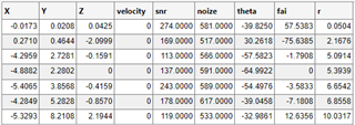
I have got point cloud and ADC raw data simultaneously using AWR1843AOP+DCA1000EVM. 

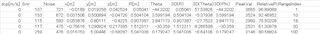
Point cloud data with range CFAR=15dB setting is the following image; 

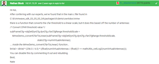
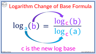
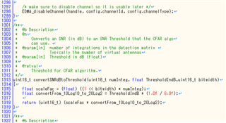
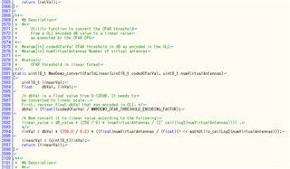
Also, I understand that "dB unit of SNR" is "SNR of DPIF_PointCloudSideInfo" / 10 from the following thread; 

https://e2e.ti.com/support/sensors-group/sensors/f/sensors-forum/1382079/awr1843aop-peakval-variable/5289608?tisearch=e2e-sitesearch&keymatch=%20user%3A560047#5289608 

Q) When r(Range) is 5.0914, snr is 113 from the above point cloud data. 

 Thus, "dB unit of SNR" is 11.3dB. I have Range CFAR set to 15dB. 

 Why is target detected with SNR below CFAR threshold(15dB)? 

Please advise. 

Regards, 

Shoko 

  • Hi,

    Could you please provide us more information about the target SW used?

    Are you using the mmWave demo?

    Thank you

    Cesar

  • Hello Cesar, 

    Yes, I'm using the mmWave demo of mmwave_sdk_03_06_02_00-LTS. 

    Regards, 

    Shoko 

  • Hello Cesar, 

    Is my problem the same as the following thread? I'm using three TX antennas in AWR1843AOP. 

    Is it a bug of the main.c?? 

    https://e2e.ti.com/support/sensors-group/sensors/f/sensors-forum/1123346/iwr6843aopevm-cfar-ca-or-cfar-caso 

    Regards, 

    Shoko 

  • Hello Cesart, 

    I have found the parameter "* 3/4" in main.c of mmwave_sdk_03_06_02_00-LTS\packages\ti\datapath\dpc\objectdetection\objdethwa\test. 

    (Please see the following image. )

    Is it related to detecting target with SNR below CFAR threshold(15dB)? 

    If yes, please let me know in detail the need to adjust thresholdScale when numTXAntenna is 3. 

    I can't understand it with only the comment in main.c. 

    Thanks, 

    Shoko 

  • Hello

    When can you give me an answer? 

    Thanks, 

    Shoko 

  • Hello, some further research is needed and I will get back to you in a few days.

    Thanks,

    Gigliotti

  • Hello Gigliotti, 

    Noted. I'm waiting for your response. 

    Thank you, 

    Shoko 

  • Hi Shoko

    Please try to comment out the code that is specified in the prevoius E2E you sent. 

    e2e.ti.com/.../iwr6843aopevm-cfar-ca-or-cfar-caso

    Specifically the instruction specified here and let me know if that resolves the issue. Once commented out, rebuild the project and try to run again.

    Best,

    Gigliotti

  • Hello Gigliotti, 

    Thank you for your reply. 

    I tried to comment out the following term of the formula in MmwDemo_convertCfarToLinear() function. 

      linVal = dbVal * (256.0 / 6.0); // * ((float)numVirtualAntennas / (float)(1 << mathUtils_ceilLog2(numVirtualAntennas))); 

    I set 0dBsm target at 5m with Target simulator. CFAR setting is "Range=CFAR_CASO, 15dB" and "Doppler=CFAR_CA, 15dB". 

    Before commenting out: 

    After commenting out: 

    As a result, AWR1843AOP detects nothing after commenting out. 

    1) Please let me know the reason for not detecting after commenting out. 

    2) I think that the formula has important implications for CFAR algorithm. 

    Please let me know any TI documents explaining the formula. 

    Please advise. 

    Regards, 

    Shoko 

  • Hello,

    A few questions before we continue. What specifically is flashed on the board? How are you changing the range CFAR to 15 db? Also where are you getting the data structure that you are receiving? Also in the meantime there is documentation for the CFAR algorithm at this file path "mmwave_sdk_03_06_00_00-LTS/packages/ti/datapath/dpc/dpu/cfarcaproc/docs/doxygen/html/index.html"

  • Hello Gigliotti, 

    I answer your questions; 

    > What specifically is flashed on the board? 

    --> I flushed the mmWave demo of mmwave_sdk_03_06_02_00-LTS to the board, I said before. 

    > How are you changing the range CFAR to 15 db? 

    --> The cfg file set to cfar=15 is loaded when IWR1843AOP starts up. 

    Also where are you getting the data structure that you are receiving? 

    --> Please see the following my thread (Please omit "RelativePe" Column); 

    e2e.ti.com/.../5289608

    > Also in the meantime there is documentation for the CFAR algorithm at this file path "mmwave_sdk_03_06_00_00-LTS/packages/ti/datapath/dpc/dpu/cfarcaproc/docs/doxygen/html/index.html"

    --> I have already read this document. Unfortunately, it does not explain the formula. That is why I have asked you. 


    1) Please let me know the reason for not detecting after commenting out. 

    2) I think that the formula has important implications for CFAR algorithm. 

    Please let me know any TI documents explaining the formula. 

    If you don't know, please change the person in charge about these questions. 

    Regards, 

    Shoko 

  • So under further investigation the formula is not supposed to be commented out in your case. It is just a change of base formula.

    Regarding documentation for the CFAR algorithm there are many resources online that you can find. It is not a TI specific algorithm.

    To move forward please provide the complete configuration file that you are sending to the board.

  • Hello, 

    > Regarding documentation for the CFAR algorithm there are many resources online that you can find. It is not a TI specific algorithm.

    --> I have already found some reference about CFAR on online but there is no mention of this formula. 

     Could you please provide some examples of resources online about this formula?? 

    > To move forward please provide the complete configuration file that you are sending to the board. 

    --> Please see the attached file. 

    Awr1843_AOP.cfg

    Regards, 

    Shoko 

  • Hello,

    First, regarding the formula it is just a change of base formula. I am not exactly sure how the code mirrors the formula but this is it. (make sure to uncomment out the formula in your code)

    Second, I would like to ask where did you acquire that .cfg from the SDK. It appears you took a profile from the xWR64xx_compression folder and modified it from there (correct me if I am wrong).

    Please use a .cfg file from this folder 

    C:\ti\mmwave_sdk_03_06_02_00-LTS\packages\ti\demo\xwr18xx\mmw\profiles\

    There are two profiles you can use based on your application, profile_2d_aop.cfg or profile_3d_aop.cfg. 2d aop utilizes 2 TX antenna while 3d aop uses 3 TX antenna. Both profiles have their range and doppler CFARs set to 15 db.

    Please try this and let me know if this resolves your issue

    Best,

    Gigliotti

  • Hello, 

    > First, regarding the formula it is just a change of base formula....

    --> No, your explanation is just "*1/6" part of the following fomura. 

       linVal = dbVal * (256.0 / 6.0); // * ((float)numVirtualAntennas / (float)(1 << mathUtils_ceilLog2(numVirtualAntennas))); 

    I think the core of the "Why is target detected with SNR below CFAR threshold(15dB) when TX antennas is three? " is "* ((float)numVirtualAntennas / (float)(1 << mathUtils_ceilLog2(numVirtualAntennas)))" part of the formula. 

    I just want to know any TI documents explaining the part of the formula. 

    > Second, I would like to ask where did you acquire that .cfg from the SDK.

    --> I made cfg by myself referencing mmwave_sdk_user_guide. 

    > Please use a .cfg file from this folder

    C:\ti\mmwave_sdk_03_06_02_00-LTS\packages\ti\demo\xwr18xx\mmw\profiles\

    --> I tried but the situation did not change all all. 

    Is the person who wrote the fomura in main.c of mmwave demo still employed at TI?

    If you know that person, could you please ask these questions to the person? 

    Regards, 

    Shoko

  • Hi Shoko,

    Thank you for your patience. So the team that worked on this code is no longer at TI unfortunately. I will be receiving help to decipher the code and hopefully by tomorrow we will be able to provide further assistance.

    Best,

    Gigliotti

  • Hi Gigliotti, 

    I have checked some source code in examples of radar_toolbox_2_10_00_04 to see how "formula for cfar threshold" is described. 

    ADAS: 

    radar_toolbox_2_10_00_04\source\ti\examples\ADAS\medium_range_radar\src\1843\dss\dss_main.c

    Area_Scanner (for 6843): 

    radar_toolbox_2_10_00_04\source\ti\examples\Area_Scanner\src\6843\mss\mss_main.c

    What is the difference between the above formula for cfar threshold

    The source code for ADAS doesn't have "* ((float)numVirtualAntennas / (float)(1 << mathUtils_ceilLog2(numVirtualAntennas)))" part. 

    Regards, 

    Shoko 

  • I am looking into why these differences are there for the MRR demo. In the meantime, it could be worth trying this conversion since the MRR demo was meant to be used with 3 TX.

    Best,

    Gigliotti

  • Hello, 

    From Piyush's reply in the following thread, the difference between the formula for cfar threshold may be the difference between using HWA or DSP. 

    e2e.ti.com/.../iwr1443boost-cfar-threshold-format-clarification

    I have read the above thread but I still don't fully understand it. 

    If Piyush's reply in the thread is an answer of my question, please explain it in an easy-to-understand way? 

    Regards, 

    Shoko 

  • Hello,

    The info I was able to retrieve for the difference in these two equations is that the MRR demo was written in parallel with SDK 3.6 and was written by a different team. Hence the slight difference but again they accomplish the same task.

    Best,

    Gigliotti

  • Hello, 

    Noted. I'm waiting for your response. 

    Shoko 

  • Hello

    When can you give me an answer? 

    Thanks, 

    Shoko 

  • Hello TI team member, 

    Could you please provide an update? 

    Regards, 

    Shoko