This thread has been locked.

If you have a related question, please click the "Ask a related question" button in the top right corner. The newly created question will be automatically linked to this question.

LDC1614: Strange oscillations measured over time

Part Number: LDC1614

Tool/software:

this is a followup for the following thread: https://e2e.ti.com/support/sensors-group/sensors/f/sensors-forum/1365269/ldc1614-strange-oscillations-measured-over-time/5213480

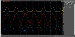
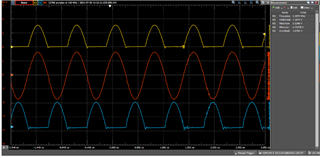
  • Could you measure the sensor waveforms on an oscilloscope while they are having the noisy behavior? By taking a differential across the INxA and INxB pins, you should see a clean sinusoidal wave. Additionally, you can double check the amplitude of the wave is between 1.2V and 1.8V during the noisy behavior. 

I took oscilloscope measurements of the signal amplitude, and I can see that the amplitude changes between measurements, and that they match with the measured frequency. The current drive code is constant at 19. We are turning the LDC1614 on and off with a mosfet between measurements. The oscilloscope measurements are attached to this post. There is no target in front of the antenna and its environment only slightly changes due to small temperature differences.

  • Do you know what the Q factor of your LC tank on each sensor channel is? 

The Q factor is 143.

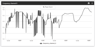
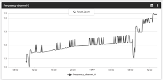
  • You mention the frequency shift due to temperature change causes a difference in the measurement noise. Does this also occur if you alter the frequency through a normal target interaction while maintaining a stable temperature? 

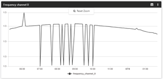
When maintaining a stable temperature we can see that the measurement noise is stable as shown in the attached photo.

Recorded values.pdf

Thanks!

  • Hello, 

    Thank you for the additional information on this. I have a few follow up questions for you to help debug this: 

    • Is this happening on multiple boards or just one? 
    • Are you using an external clock or the LDC1614 internal clock? 
      • If external, can you check the stability of it with the oscilloscope compared to the noise spikes on the LDC1614 waveform? 
    • Can you check the stability of your power supply against the noise on the sensor waveform? 
    • While these tests are occurring, is just one sensor channel active or both? 
      • Can you try with just one sensor channel active if not already doing so? 

    Best Regards, 

    Justin Beigel

  • Hi Justin,

    Is this happening on multiple boards or just one? 

    This is happening on multiple boards

    Are you using an external clock or the LDC1614 internal clock?

    Yes, but it is stable when measured with a scope.

    While these tests are occurring, is just one sensor channel active or both? 

    I tried with 2 sensor channels and one sensor channel.

    I did try to leave the sensor powered on all the time and it seemed to fix the issue of the value changing.

    I also observed that the oscillation in frequency is not a measurement error, but is caused by the fact that the amplitude is different between each measurement, resulting in a different measured value.

    Here are some example of measurements.

    For the following picture, I stopped powering down the LDC1614 right before the 12/07 mark.

    The next step for us will be to check the power consumption while the sensor is in sleep.

    This is a low-power application, which is why we initially switched off the power to the sensor.

    Best regards,

    Étienne Machabée

  • Hello, 

    When you are experiencing the issue, are you taking the data from the first measurement cycle after power up? If so, what happens if you just collect 2 or three samples after power up? Additionally, can you provide what the status register reports for these measurements? 

    Best Regards, 
    Justin Beigel

  • I collect 20 samples after power up, over the span of 20 seconds.

    Here is the status register for the measurement:

    00> <info> app: LDC1614 status:
    00>
    00> <info> app: Error Channel: 0
    00>
    00> <info> app: Conversion Under-range Error: 0
    00>
    00> <info> app: Conversion Over-range Error: 0
    00>
    00> <info> app: Watchdog Timeout Error: 0
    00>
    00> <info> app: Sensor Amplitude High Error: 0
    00>
    00> <info> app: Sensor Amplitude Low Error: 0
    00>
    00> <info> app: Zero Count Error: 0
    00>
    00> <info> app: Data Ready Flag: 1
    00>
    00> <info> app: Channel 0 Unread Conversion: 0
    00>
    00> <info> app: Channel 1 Unread Conversion: 0
    00>
    00> <info> app: Channel 2 Unread Conversion: 0
    00>
    00> <info> app: Channel 3 Unread Conversion: 1

    The only thing changing is which channel has an unread conversion.

  • Hi Justin,

    I have tried sleeping the LDC1614 instead of cutting off the power to it. I left the oscillator on. I still get the same results.

    Could it be cause by an ADC calibration? We manually set the IDrive current. Could it be overridden somehow by the chip?

    Thanks

    Étienne Machabée

  • Hello, 

    When you manually set the IDRIVE, are you also setting the RP_OVERRIDE_EN and AUTO_AMP_DIS bits of the CONFIG register? Without those set, the LDC1614 will not properly take your IDRIVE setting. 

    If you are cutting power to the LDC1614, you would have to re-write the device settings on startup again but just sleeping the device would not have this issue. 

    One other test to try, from the other thread, it was mentioned that the deglitch filter is set to 10MHz. With just the one channel enabled, can you set the deglitch filter to 3.3MHz to see if it helps in this case? 

    Best Regards, 
    Justin Beigel