This thread has been locked.

If you have a related question, please click the "Ask a related question" button in the top right corner. The newly created question will be automatically linked to this question.

LM95233: LM95233 SCH review and Layout suggestion

Part Number: LM95233
Other Parts Discussed in Thread: TMP1826, TMP468

Tool/software:

Dear TI Team:

We have LM95233 in our design, \

1. Could you pls review the SCH attached, thanks

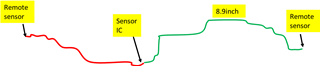
2. We will have the remote sensor far away from sensor IC, the plan path is as below,

one on the left and the other one is on the right, which may be 9inch faraway from sensor IC,

Is it OK?

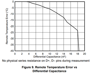
3. Could you suggest the distance between remote sensor(BJT/Diode) and Sensor IC(LM95233)?

And why has this distance restrict?

thermal Sensor SCH.pdf

Best Regards

Lisa

  • The schematic is fine.

    Nine inches is possible. Distance is normally limited by capacitance of cabling. The LM95233 can only tolerate ~300pF when TruTherm is enabled and ~3nF when TruTherm is disabled. Note that TruTherm is enabled for channel 1 by default. The capacitor on your schematic sums with any cable capacitance, so the capacitor may need to be removed.

    Induced noise can be a problem for remote sensors, especially when the signal passes near an EMI source. The current levels for the transistor must be very small, in the micro amp range, and this makes them vulnerable. If this is a concern for your application, I would recommend using a local temperature sensor at each sensing node. TMP1826 has a 1-Wire interface that can operate over two conductor cabling.

    thanks,

    ren

  • Hi Ren:

    Thanks for your reply.Due to it is my first time to use thermal sensor, Some confusion need your help

    1. What is the difference when TruTherm is enabled or disabled?

    2. Why the capacitance restriction is higher(~3nF) when ThuTherm is disabled than enabled?

    3. Distance is normally limited by capacitance of cabling

    ==>Could you explan more detail how the capacitance impact distance then impact thermal detect performance?

    4. For capacitance calculation:

    It is the capacitance to Ground or the capacitance between D+ and D-.

    4.1 If it is capacitance to gound, the trace capacitance can be calculated by Co, 

    Sum = trace capacitance + device pin capacitance(normally 10pF max), Right?

    And the 100pF between D+/D- will not be added, right?

    4.2  If It is the capacitance between D+ and D-. How to calculate the trace capacitance?

    Best Regards

    Lisa

  • 1. TruTherm is for embedded junctions, and does not apply to your application with 3904 transistors

    2. The behavior of the analog front end changes.

    3. Excessive capacitance will create excessive negative temperature error, as seen in this plot from TMP468 datasheet. The LM95233 architecture is different than TMP468. LM95233 datasheet charts don't show the failure point for excessive capacitance, so we can't see the same effect. This error will occur on all remote sensors due to inability to settle before ADC sampling.

    4. Both contribute to settling time. Your CAD tools may be able to calculate trace capacitance. It will vary somewhat based on materials used.

    ren

  • Hi Ren:

    Thanks for your explanation. 

    For Items 4, it means the D+/D- should has enough gap to minimun the capacitance between D+/D-,Right?

    And if the trace is too long, I can delete the 100p cap on D+/D- to minimun total capatance,Right?

    Best

    Lisa

  • Here's an article on parasitic capacitance from a PCB fab: https://www.protoexpress.com/blog/how-to-reduce-parasitic-capacitance-pcb-layout/

    Yes, you can omit the 100pF cap. It's not required for operation, but may help in noisy environments.

    On the topic of noise, it's recommended to shield D+/D- traces as shown in this app note. https://www.ti.com/lit/sboa173

    thanks,

    ren

  • Hi Ren:

    Thanks for your kindly and nice reply.

    Best

    Lisa