This thread has been locked.

If you have a related question, please click the "Ask a related question" button in the top right corner. The newly created question will be automatically linked to this question.

OPT3101: Walk-error

Part Number: OPT3101

Tool/software:

Hello,

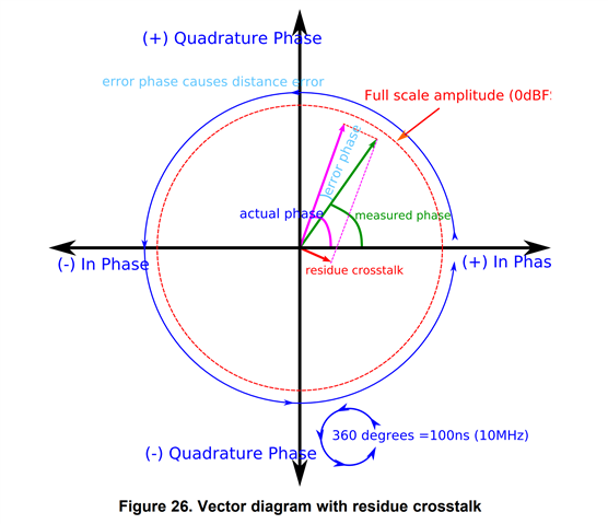
OPT3101 is using an Indirect TOF method with phase measurement after I/Q demodulation.

For Direct TOF systems, a well-known error is the Walk-Error.

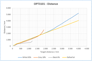
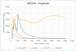
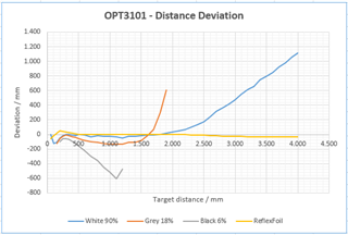
Also with our OPT3101 devices, we observe a distance (= phase) error in dependency of the signal amplitude (= reflectance of the target).

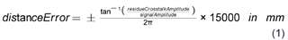
What is the physical / mathematical correlation between the signal amplitude and the phase at OPT3101 ITOF method?

Thanks.

  • Hi Stefan,

    In practical iToF system, the phase shift measurement can be influenced by the signal amplitude. Higher signal amplitudes can lead to a slightly different phase shift compared to lower amplitudes due to the non-linearities in the sensor electronics or optical components. This correlation can introduce an error in the phase measurement leading to inaccurate distance calculations. 

    If the signal amplitude is too high, it can saturate the sensor, which distorts the measured phase. 

    Proper calibrations can mitigate these errors. 

    How many parts have you found the error? What calibrations did the parts go through?

    Thank you.

    Wenjuan

  • Hello Wenjuan,

    we tested more than 20 parts now.

    Our system is similar to OPT3101 EVM. We used the ConfiguratorTool (Super-HDR-Mode) and did all the calibration according to the user guide "How to set up and calibrate OPT3101 based systems for proximity sensing", with the help of the SDK.

    Following some measure data. It can be seen, that there is a distance deviation between the different targets, especially when the signal amplitude is getting smaller.


    Thank you.

    Stefan

  • Hi Stefan,

    After calibration, what is the amplitude with the photodiode covered? The uncorrected non-zero amplitude after calibration is considered as residue crosstalk and it is crucial to determine the absolute accuracy of the system.

    As distance increases, the received signal amplitude reduces, so same level of crosstalk error will result in higher distance error. 

    What LED and PD do you use? How does it compare against the OPT3101ESTIMATOR-SW Simulation tool | TI.com for similar conditions?

    Do you see the same issue on all the 20 parts?

    Thank you.

    Wenjuan

  • Hello Wenjuan,

    We observe the same issue on all parts.
    We use PD SFH2400 and a red light TOPLED LED.

    Thank you for your hint at residue crosstalk and the Estimator Tool.
    The simulation more or less corresponds to our system.

    The residue crosstalk varies in the range 0...400, with a strong temperature drift. So I think this is an issue of temperature deviation / compensation.

    The correlation between signal amplitude and phase / distance error seems to be:

    The distanceError can have a positive and a negative sign.

    Is there some correlation to figure out, if the current error has positive or negative sign?
    Is it maybe correlated to the current phase?

    Thank you.

    Stefan

  • Stefan

    Crosstalk of 400 is high - do you only see the high crosstalk when there is a fast temperature change such as power reset or LED current switching as you discussed in temperature deviation / compensation? Did you have any change after all calibrations?

    Figure 26 in document "Introduction to Time-of-Flight Long Range Proximity and Distance Sensor System Design" described the residue crosstalk impact on distance error. Positive or negative depends how the residue crosstalk vector line up and there is no mechanism to determine the sign. 

    Thank you.

    Wenjuan

  • Hi Wenjuan,

    We see high residue crosstalk right after power reset. Crosstalk then decreases down to < 20, and rises again up to even 500 (at my DUT today).

    So, we have a strong temperature drift.

    After re-calibration of optical crosstalk, the residue crosstalk starts with < 20, then slowly rises again up to 100.

    When we deactivate temp. correction (en_temp_corr; en_temp_xtalk_corr) the residue crosstalk stays in the range < 30.

    Thank you.

    Stefan

  • Stefan,

    The crosstalk is decreased after re-calibration, and residue crosstalk is less when you deactivate the temp. correlation, looks some issue with the calibration. 

    Is it the same calibration as you talked in OPT3101: Temperature deviation - Sensors forum - Sensors - TI E2E support forums?

    Thank you.

    Wenjuan