This thread has been locked.

If you have a related question, please click the "Ask a related question" button in the top right corner. The newly created question will be automatically linked to this question.

AWR2243: TIDA-020047 AM2732+AWR2243 issue

Part Number: AWR2243
Other Parts Discussed in Thread: AM2732, TIDA-020047, MMWAVE-MCUPLUS-SDK

Tool/software:

Dears,

  The customer is using TIDA-020047 source files to manufacture the board, with main chips AM2732+AWR2243. There is an issue with cascading the two IC.

The detailed description of the problem can be found in the attached Word document

TIDA-020047 AM2732+AWR2243 issue.docx

  • Hi,

    I would need some additional info here to get more insight into the problem:

    1. Have you performed phase calibration before obtaining the plot? Does the plot look the same after the phase has been corrected?
    2. Can you let me know what you mean exactly by single IC and dual IC firmware? Can you tell me the name or path of the same? Both the AWR2243 devices use the same firmware, and the same patch is to be used on both as well.
    3. Does this "false alarm point" remain even after:
      1. Changing the sampling rate or slope?
      2. Changing the test object or test scene?
    4. What is the exact waveform you have implemented to obtain this data? (Profile and chirp config info)

    Regards,

    Kaushik

  • 1. Channel consistency issue, the customer also suspects phase calibration and is currently debugging;
    2. False alarm issue, the customer found a false alarm point at position 229 when flashing the AWR2243 dual chip firmware on the same device. However, when testing the AWR2243 single chip firmware, it was found that there was no false alarm point. The testing scenario was a radar facing the sky to ensure the same environment;
    3. All devices on hand have this issue, including TI's official design and development board, as well as our self-developed board, located at 229;
    4. Waveform configuration profileCfg 0.0000 77.0000 5.0000 5.0000 17.3800 0.0000 0.0000 11.0000 0.0000 256.0000 22500.0000 0.0000 0.0000 0.0000 0.0000 180.0000;
    5. The distance unit has been changed to 192, but the false alarm point is still present;

  • Hi,

    Thank you for your feedback. Please find my responses as below:

    1. Please let us know the feedback of this debug.
    2. I'm still not sure if I understand what has been used for this testing. Can you please provide details on the firmware name and version accurately?
    3. Thanks for the confirmation. This will make it easier to reproduce the issue on our end if required.
    4. Thank you for the sharing this. Do you also have any phase shifter configured?
    5. Can you let me know exactly what was changed here when you mean distance? Can you let me know the impact of changing the sampling rate or the slope.

    Regards,

    Kaushik

  • Dear,

    1.The customer is following the instructions in“Cascade Coherency and Phase Shifter Calibration Application Note”(www.ti.com/.../SPRACV2)  and will feed back the debugging result as soon as possible.


    2. The  evaluation module is TIDA-020047 (Two-device mmWave cascade reference design for automotive 4D imaging radar)and the firmware is required from TI FAE named“mmWave2ChipCascade_30_June_2023.zip”.


    3. The false alarm point remains when flashing another single-chip venison firmware into the same evm board. The firmware is downloaded from url
     “www.ti.com/.../MMWAVE-MCUPLUS-SDK” and can be found in the directory path 
    “ti\mmwave_mcuplus_sdk_04_04_01_02\mmwave_mcuplus_sdk_04_04_01_02\ti\demo\am273x\mmw” 


    4.The firmware is using doppler diversity multiple access mode and the phase shifter configured is by default.Exactly, the phase degree of first transfer antenna TX1 is shifting as this mode “ 0°, 0°, 0°, 0°...” and the TX2 is “0°,45°,90°,135°...” and the TX3 is “0°,90°,180°,270°...”and so on.


    5.The former waveform configuration is “profileCfg 0.0000 77.0000 5.0000 5.0000 17.3800 0.0000 0.0000 11.0000 0.0000 256.0000 22500.0000 0.0000 0.0000 0.0000 0.0000 180.0000”.When changing the slope from 11 to 35, the range profile is still abnormally high on range bin 229. When changing the range bin parameter from 256 to 192, the range profile is abnormally high on range bin 172. Because 172/192 equals to 229/256, so we multiply this  ratio by sampling rate 22.5MHz and guess there may exist a 20MHz radiation leakage in RF receiver. However, when changing the sampling rate from 22500 to 21000,the range profile is high on range bin 25 and 196, where the power is slightly lower than that of sampling rate 22500 and is not correspond to 20MHz frequency.For comparison,when changing the sampling rate from 22500 to 20000, or using the single-chip venison firmware instead, the range profile seems normal on range bin 229. Therefore, we are puzzled with such phenomenon.

  • Hi,

    Thak you for your response. Please find my feedback below:

    1. Please let us know as you obtain more information,
    2. Can you please ask the TI FAE to get into touch with me? There is a later version of this code which you can migrate to. I can share it with you through the FAE.
    3. What you have pointed out here is the SDK version. Can you let me know the mmWave DFP version that you are using in either case? Is it the same as the one available in the SDK?
    4. Is the phase shift done only on one of the 2 AWR2243s? Typically, the DDMA modulation changes for 6Tx based system. Can you please confirm your phase shift across both the devices?
    5. Thank you for the confirmation. I have some follow up questions here:
      1. Where did you obtain this data from? Was it directly from the ADC buffer or did you perhaps take it after the range processing from the SoC?
      2. If you take the data from the devices individually, do you see this spurious signal on data from both of the devices or only one of the devices?
      3. Is the spur seen on all the receiver channels or only on some?
      4. Is the spur also seen across all chirps or only a small subset?
    6. If you have a test object in the scene, is there any dependency on the object on this spur (i.e is there any SNR drop or bin shift)?
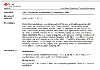
    7. Here was one erratum that would lead to spurs at some certain sampling rates for reference. Please make sure that this is not occurring in your case. Also, this erratum does not mention any conditions for cascading and the effect of cascading. 

    Regards,

    Kaushik