This thread has been locked.

If you have a related question, please click the "Ask a related question" button in the top right corner. The newly created question will be automatically linked to this question.

FDC2214: Active Shield Prevents Drive Strength Changes

Part Number: FDC2214
Other Parts Discussed in Thread: BUF602

Tool/software:

I'm hoping someone here can shed some light on a problem we are having with our prototype liquid level sensor and active shielding.

With the shield buffer in-circuit, the sensor peak voltage rises to a large-ish value (3 to 4 volts) no matter what drive setting I tell the FDC.

Removing the output of the buffer from the shields, then the levels are fine.

Circuit:

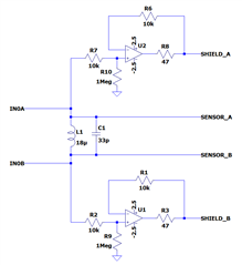
We are using a differential sensor configuration so we are driving both electrodes' shields with buffers from their respective output of the FDC.

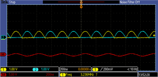
Here is the LC tank + sensors signal without buffers activated:

And here it is with the buffers on (no change to drive strength register):

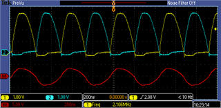
Here are the outputs of the buffers:

Troubleshooting steps we have tried to no avail:

  • Replace the 10kΩ's with 10Ω.
  • Change the 47Ω to 0 and place 22Ω outside the loop on the output.
  • Remove the 1MΩ
  • Remove the output of just the B side buffer.
  • Cut the B side sensor to try out single ended configuration. A side buffer on.

Other info that might be pertinent:

  • The 2.5 volt supplies are LDO's and look clean on the scope.
  • The layout is not the best and likely large-ish parasitic capacitance between LC tank and buffers.
  • The PCB is all flex, so there is not very much thickness of dielectric between sensor electrode and shields.

Thanks.

  • Griffin,

    Just confirm:

    1. With the buffers inputs connected to the sensor, but the buffer outputs not connected to the shield, the sensor waveforms look okay?
    2. If the buffer outputs are then connected to the shields, the signals become tool large & distorted?
    3. Are the buffers always powered-up, even when they aren't connected to the shields?

    If this is correct:

    1. What op amp are you using?
    2. What is the op amp's GBW, slew rate, max output swing and its ability to drive capacitive loads?
      Assuming the shields have some decent capacitance, they may compromising the buffers' stability.

    Some quick experiments to see if they affect the overall behavior:

    1. Add some varying & small series R between the shields and the buffers' outputs.
    2. Try adjusting the buffers' power supply Example: {-2.5V,+2.5V} → {-1V,+4V}
    • With the buffers inputs connected to the sensor, but the buffer outputs not connected to the shield, the sensor waveforms look okay?
    • If the buffer outputs are then connected to the shields, the signals become tool large & distorted?
    • Are the buffers always powered-up, even when they aren't connected to the shields?

    1. Correct.

    2. Correct.

    3. They are always powered up.

    • What op amp are you using?
    • What is the op amp's GBW, slew rate, max output swing and its ability to drive capacitive loads?
      Assuming the shields have some decent capacitance, they may compromising the buffers' stability.

    1. STM TSV791ILT

    2. 50MHz, 30V/us. The datasheet mentions that 22 Ω on the output is "sufficient to make the TSV79x stable whatever the capacitive load." Which we tried, but it did not help.


    However, we changed to a buffer IC (BUF602) and ended up with 100 Ω on the output of that to finally make a stable shield and resonator on the FDC.

  • Griffin,

    Is your system working now that you have introduced the BUF602?

    Regards,
    John