This thread has been locked.

If you have a related question, please click the "Ask a related question" button in the top right corner. The newly created question will be automatically linked to this question.

AWR6843ISK: AWR6843ISK

Part Number: AWR6843ISK
Other Parts Discussed in Thread: TIDEP-01023

Tool/software:

Hi ,

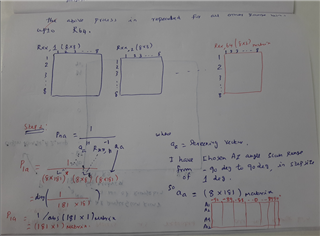
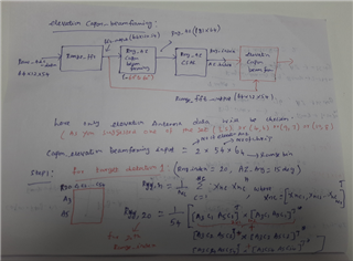
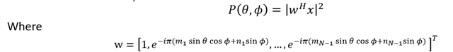
the mentioned  formula is  used to implement capon (ie mVDR))beam forming .

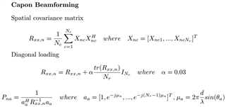
I have seen in matlab that MVDR beamforming is implemented using  below formula

   mvdr = 1./real(sum(sv'.*(Cx\sv).',2));

   where Sv- streeing vector

             Cx- covariance matrix inverse

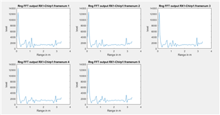
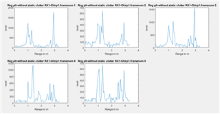
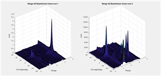
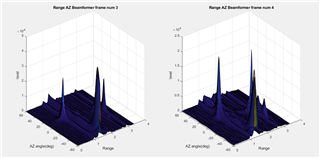
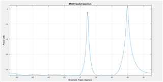
i have attached sample matlab example code and its result for your reference.

%%%%%%MVDR (Capon) spatial spectrum estimator for ULA

fs = 8000;
t = (0:1/fs:1).';
x1 = cos(2*pi*t*300);
x2 = cos(2*pi*t*400);
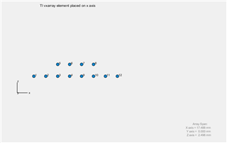
array = phased.ULA('NumElements',10,'ElementSpacing',1);
array.Element.FrequencyRange = [100e6 300e6];
fc = 150.0e6;
x = collectPlaneWave(array,[x1 x2],[10 20;60 -5]',fc);
noise = 0.1*(randn(size(x)) + 1i*randn(size(x)));

estimator = phased.MVDREstimator('SensorArray',array,...
'OperatingFrequency',fc,'DOAOutputPort',true,'NumSignals',2);

[y,doas] = estimator(x + noise);
doas = broadside2az(sort(doas),[20 -5])

plotSpectrum(estimator)

%%%

My question:

 1.Can you confirm what is the difference between capon beamforming used in your case and  implemented in matlab using "mvdr = 1./real(sum(sv'.*(Cx\sv).',2)); "?

  2.does both implement the same thing or different? can you elaborate about it?

regards,

mani   

  • Hi,

    Thanks for posting. Please allow us a day or so to follow up.

    Thanks gain,

    Clinton

  • Hey Mani,

    Thanks for reaching out regarding your question on MVDR. First of all, I'm unfamiliar on the complete implementation of MATLAB's MVDREstimator function besides the equation you've outlined. However, the main difference between our MVDR implementation and the traditional MVDR implementation is that we apply a diagonal loading factor, alpha (sometimes specified as gamma), to the covariance matrix to help improve robustness of the beamformer.

    As alpha approaches infinity, the beamformer's behavior starts to resemble the standard beamformer/digital beamformer (DBF). Conversely, as alpha approaches 0, the beamformer's behavior starts to resemble the traditional MVDR beamformer. Therefore, we can use this alpha parameter to mix between the two beamformer behavior's which we've found 0.03 to be optimal for most of our applications.

    It doesn't appear a diagonal loading factor is used in the MATLAB implementation, so I would wager that the MATLAB MVDR is a traditional MVDR.

    Regards,

    Kristien

  • Dear kristien,

     thanks for your quick reply.

    i have captured ADC data using AWR6843ISK+DCA 1000 card for the following Chirp design parameter and trying to implement capon beam forming as per the equation used by you:

    system parameter:
    Maximum range - 2.7 m
    Range resolution - 0.053 m
    Maximum velocity - 0.406 m/s
    velocity resolution - 0.015 m/s

    chirp design 1:
    profileCfg 0 60 943 11 41 0 0 97 1 64 2200 0 0 30
    channelCfg 15 7 0
    adcbufCfg -1 0 1 1 1
    chirpCfg 0 0 0 0 0 0 0 1
    chirpCfg 1 1 0 0 0 0 0 2
    chirpCfg 2 2 0 0 0 0 0 4
    frameCfg 0 2 54 0 200 1 0

    antenna pattern attached for your reference:

    I have used the same capon beamforming equation  and calculating Range_Azimuth spectrum .(step by step calculation screenshots attached below for your  reference):

    My question:

      1. please check and confirm the above steps, am i calculating range-azimuth spectrum correctly or is there any mistake in my calculation?

    regards,

    Mani

  • Hey Mani,

    Give me a day or two to look into your diagrams here.

    Regards,

    Kristien

  • hi kristien,

       have you checked it the diagram and flow.

      please confirm the above steps, am i calculating range-azimuth spectrum correctly or is there any mistake in my calculation?

    Regards,

    Mani

  • Hey Mani,

    Sorry for the delay. Another one of our signal processing experts will reply within the next day.

    Regards,

    Kristien

  • HI, Mani:

    Your diagram looks good to me.  Let me know if you experience any difficulty that make you doubt your implementation.  

    Best,

    Zigang

  • hi zigang,

      thanks for your reply.

      i have attached AWR6843ISK card antenna pattern for your details

    i have captured real time data using AWR6843ISK + DCA 1000 card for the followings two  test cases of antenna Transmission order.

    for both test cases ,Virtual antenna used and antenna elements positions used to generate steering vector(which is used part of Capon beam forming )also shared for your reference.

    Case 1:

           Chirps are transmitted using following TX antenna:

                            Chirp1 - TX1

                            Chirp2 - TX2

                            Chirp3 - TX3

                  (the same way chirps are repeated in the remaining active chirp transmission time )

    I have attached  virtual array generated and used inside my code:

    Virtual array element positions:

    Antenna elements used for capon beamforming:

    Sno

    Antenna elements used for Rng-AZ capon beam forming

    Antenna elements used for Elevation capon beam forming

    1

    [1,2,3,4,9,10,11,12]

    [1,2,3,4,5,6,7,8,9,10,11,12]


    Case 2:

           Chirps are transmitted using following TX antenna:

                            Chirp1 - TX1

                            Chirp2 -TX3

                            Chirp3 -TX2

                  (the same way chirps are repeated in the remaining active chirp transmission time )

    I have attached virtual array generated and used inside my code:

    Virtual array element positions:

    Antenna elements used for capon beamforming:

    Sno

    Antenna elements used for Rng-AZ capon beam forming

    Antenna elements used for Elevation capon beam forming

    1

    [1,2,3,4,5,6,7,8]


    [1,2,3,4,5,6,7,8,9,10,11,12]


    my question:

     please check and confirm me, whether Antenna elements chosen for capon beamforming(Both Rng-azimuth and elevation) are correct for both test cases 1 and 2?

    regards,

    mani

  • Hi,

    Thanks for posting. This is a holiday week in the U.S. We will follow up early next week.

    Thanks,

    Clinton

  • HI, Mani:

    If you are using 1D azimuth capon beamforming, all the antenna used has to be with the same elevation index.   

    If you are using 1D elevation capon beamforming, all the antenna used has to be with the same azimuth index. 

    Based on the above rule, the antenna elements you used for rng-azi is correct.  The antenna elements you used for rng-elev is incorrect.  Based on the figure below, you can use (3, 5) or (4, 6), or (9, 7) or (10, 8), i.e., you can use any of the these four sets to calculate the rng-elev beamforming.   At the end, you can sum them in power to the get the rng-elev angle spectrum in power.   Let me know if it is helpful.

    Best,

    Zigang

  • Hi zigang,

    Thanks for your response. 

    I have calculated elevation capon beamforming using the same capon equation, elevation antenna element selected as you suggested  and generated  corresponding elevation spectrum .(step by step calculation screenshots attached below for your  reference)

    Steering vector calculation for chosen elevation antennas (steps by step calculation screenshots also attached for your  reference):

    my question:

    1. please check the above  both "elevation capon beam forming  and  steering vector generation for elevation antenna chosen"  screenshot and confirm me, whether am i estimating correctly or any error in the flow?

    2. your previous reply"The antenna elements you used for rng-elev is incorrect.  Based on the figure below, you can use (3, 5) or (4, 6), or (9, 7) or (10, 8), i.e., you can use any of the these four sets to calculate the rng-elev beamforming.   At the end, you can sum them in power to the get the rng-elev angle spectrum in power"

        i did not understand the meaning of "At the end, you can sum them in power to the get the rng-elev angle spectrum in power. ",can you explain me detail or  better  way?

    Regards,

    mani

  • Hi, Mani:

    1) Sorry, we can not reviewing your algorithm in detail.  

    2) Sorry for the misunderstanding.  Since you are trying to calculate the peak from range-azimuth spectrum. Giving the peak (rng_peak, azi_peak), you calculate the elevation spectrum.  If that is the case, then you could use all the antennas, because the azimuth angle is known in this case. 

    Please ignore my previous comments.  I thought you are trying to calculate range-elevation heatmap without knowing the azimuth angle.  

    Best,

    Zigang

  • hi zigang,

     thanks for your quick response.

    My question:

    1. your reply:"1) Sorry, we can not reviewing your algorithm in detail".the screenshot attached are not my own algorithms and I m trying to implement algorithms used part of TI reference design documents only. I request you to check and  confirm me ,whether i follow correctly or any mistake is there?

    2. your reply : " Sorry for the misunderstanding.  Since you are trying to calculate the peak from range-azimuth spectrum. Giving the peak (rng_peak, azi_peak), you calculate the elevation spectrum.  

       yes, First i m doing Rng-AZ capon beamforming then pass to CFAR to get range index and AZ value estimated .using these range index and az angle generating capon beamforming for elevation.

        you mentioned "If that is the case, then you could use all the antennas, because the azimuth angle is known in this case." please confirm are you referring which of the below all antenna numbers and orders?    

         all  antennas used for elevation capon beam forming  = [ 1  2  3  4  5  6  7  8  9  10 11 12 ]

                                          or 

          all antennas used for elevation capon beam forming = [ 1  2  3  5  4  6  9  7 10  8  11 12 ]

                                            or 

           all antennas used for elevation capon beam forming = [   3  5  4  6  9  7 10  8  ]   --->only 2 row   antennas 

                                          or

           all antennas used for elevation capon beam forming = [   3  4  5  6  7  8   9 10]   --->only 2 row   antennas 

                                    or 

                    if any other order ,please mention

    3. In case i m trying to calculate range-elevation heatmap  from range FFT output without knowing the azimuth angle. 

          your previous reply"

    If you are using 1D azimuth capon beamforming, all the antenna used has to be with the same elevation index.   

    If you are using 1D elevation capon beamforming, all the antenna used has to be with the same azimuth index. 

    Based on the above rule, the antenna elements you used for rng-azi is correct.  The antenna elements you used for rng-elev is incorrect.  Based on the figure below, you can use (3, 5) or (4, 6), or (9, 7) or (10, 8), i.e., you can use any of the these four sets to calculate the rng-elev beamforming.   At the end, you can sum them in power to the get the rng-elev angle spectrum in power.  "

    I could not understand "At the end, you can sum them in power to the get the rng-elev angle spectrum in power.  " Can you explain it?

    Regards,

    Mani

  • Hi, Mani:

    Which design document you are follow?  Please send me a link.  I was not able to recognized that you are following an algorithm used in TI demo. 

    Best,

    Zigang

  • Hi zigang,

      thanks for your reply.

      I have referred TI design document "Design Guide: TIDEP-01023 Child-Presence and Occupant-Detection Reference Design Using 60-GHz Antenna-on-   Package mmWave Sensor "

        https://www.ti.com/tool/TIDEP-01023#tech-docs

    I have implemented Rng-AZ capon beamforming, elevation beamforming as per the steps reference to this document (already screenshots of Implementation shared for your reference in previous replies)

    I request you to kindly check and confirm me,  my question on previous reply.

    My question:

    1.  I request you to check and  confirm me ,whether i follow correctly the seps of elevation capon beamforming or any mistake is there(screenshots were attached in previous reply)?

    2. your reply : " Sorry for the misunderstanding.  Since you are trying to calculate the peak from range-azimuth spectrum. Giving the peak (rng_peak, azi_peak), you calculate the elevation spectrum.  

       yes, First i m doing Rng-AZ capon beamforming then pass to CFAR to get range index and AZ value estimated .using these range index and az angle generating capon beamforming for elevation.

    you mentioned "If that is the case, then you could use all the antennas, because the azimuth angle is known in this case." please confirm are you referring which of the below all antenna numbers and orders?    

         all  antennas used for elevation capon beam forming  = [ 1  2  3  4  5  6  7  8  9  10 11 12 ]

                                          or 

          all antennas used for elevation capon beam forming = [ 1  2  3  5  4  6  9  7 10  8  11 12 ]

                                            or 

           all antennas used for elevation capon beam forming = [   3  5  4  6  9  7 10  8  ]   --->only 2 row   antennas 

                                          or

           all antennas used for elevation capon beam forming = [   3  4  5  6  7  8   9 10]   --->only 2 row   antennas 

                                    or 

                    if any other order ,please mention

    3. In case i m trying to calculate range-elevation heatmap from range FFT output  as first step itself without knowing/using the azimuth angle. 

          your previous reply"

    If you are using 1D azimuth capon beamforming, all the antenna used has to be with the same elevation index.   

    If you are using 1D elevation capon beamforming, all the antenna used has to be with the same azimuth index. 

    Based on the above rule, the antenna elements you used for rng-azi is correct.  The antenna elements you used for rng-elev is incorrect.  Based on the figure below, you can use (3, 5) or (4, 6), or (9, 7) or (10, 8), i.e., you can use any of the these four sets to calculate the rng-elev beamforming.   At the end, you can sum them in power to the get the rng-elev angle spectrum in power.  "

    I could not understand "At the end, you can sum them in power to the get the rng-elev angle spectrum in power.  " Can you explain it?

    Regards,

    Mani

  • The design you shared is obsolete that we no longer support.  Please give me some time to follow back to you. 

    Best,

    Zigang

  • Mani,

    We do not review work like this on e2e and we do not support obsolete design guides or any content that is not currently on ti.com / the latest in radar toolbox. Your questions are going beyond the scope of the e2e forum. Please make new threads with specific questions. It is important that a new thread is made for every new question.

    "1.  I request you to check and  confirm me ,whether i follow correctly the seps of elevation capon beamforming or any mistake is there(screenshots were attached in previous reply)?"

    The question above cannot be answered on this forum. If you continue to ask for things outside of the scope of the e2e forums we cannot support you. Please stay polite and follow our e2e policies.

    Thank you,

    Angie 

  • Hi Angie,

    Thanks for your reply.

    I would like to add here few points for your reference.

    I m not asking any code review..this capon beamforming  equation and implementation steps are taken from  TI applications documents available from ti website.. and also many of the applications available part of ti radar toolbox  (ex :child presence detection, people tracking ,people counting applications also uses same capon beamforming implementation and its  mentioned In their user guide and appicatikn document. And also additional point to note that  all these applications are available part of radar toolbox and not obsolescence yet).

    Note:

    Incase you wanted addition TI reference design documents, where this capon beamforming steps are mentioned..i can attach to confirm.

    I have implemented  the same capon  beamforming referring TI documents  but not getting expected results with real time data (logged using dca+ AWR6843ISK).so I have shared my implementation steps followed referring TI document for reference here  (in figure) to get fix  issues with expert..I have not shared any code  for review.

    I request you to extend possible support within the limit of e2forum policy.

    Regards, 

    Mani

    .

  • Hi, Mani:

    I just realized that although the TIDEP-01023 is no longer supported, the people counting demo still support this mode (2D range-azimuth heatmap -> peak detection -> elevation 1D heatmap). 

    1)   "If that is the case, then you could use all the antennas, because the azimuth angle is known in this case." please confirm are you referring which of the below all antenna numbers and orders?    

    [ZY]  the algorithm uses all  antennas for elevation capon beam forming  = [ 1  2  3  4  5  6  7  8  9  10 11 12 ], and the covariance matrix and its inversion is calculated using all 12 antennas.  Regarding the antenna order, as long as the order matches the steering vector generation order, it will be fine. 

    2)   In case i m trying to calculate range-elevation heatmap from range FFT output  as first step itself without knowing/using the azimuth angle. 

    If you are using 1D azimuth capon beamforming, all the antenna used has to be with the same elevation index.   

    If you are using 1D elevation capon beamforming, all the antenna used has to be with the same azimuth index. 

    Based on the above rule, the antenna elements you used for rng-azi is correct.  The antenna elements you used for rng-elev is incorrect.  Based on the figure below, you can use (3, 5) or (4, 6), or (9, 7) or (10, 8), i.e., you can use any of the these four sets to calculate the rng-elev beamforming.   At the end, you can sum them in power to the get the rng-elev angle spectrum in power.  "

    I could not understand "At the end, you can sum them in power to the get the rng-elev angle spectrum in power.  " Can you explain it?

    [ZY] Combine the spectrum in power is not optimal.  We have done this way when using Bartlett beamforming.  Consider θ is azimuth angle and ∅ is elevation angle.  The Bartlett 2D beamforming can be calculated as below.  

    If you just picked the antennas with a common m_i, and different n_j,  the phase offset (m_i * sin⁡θ  * cos⁡ϕ) is common.  When you calculate the spectrum in power, this phase offset can be ignored.   For ISK board, you can choose any 4 options below for this spectrum calculation (within the set, they all have common azimuth index m_i) .   And you can also add the spectrum in power to get some non-coherent gain.   But I am not sure whether it makes sense to combine the spectrum when using capon beamforming.  Hope it is helpful.  Given that the ISK board have two element in elevation direction, it does not make sense to start with range-elevation heatmap calculation. 

    Best,

    Zigang

  • Hi zigang,

    Thanks for your reply and detailed  explanation.

    now I understood the antenna orders need to be used for elevation  (from question:1 answered by you).

    I am also using the following order to estimate range,azimuth and elevation information .

    (Range FFT->2D range-azimuth heatmap -> peak detection -> elevation 1D heatmap).And followed reference equation and  step by step flow explained part to TI design documents.

    And I have tested  implemented chain with real time adc level data (logged using dca+ AWR6843ISK) but not getting expected results at capon rng_Az beamforming and so i want to get fix the issues.

    Please confirm whether I can share the test results snapshots part of this thread pr need to create a new thread..so I will do accordingly .

    Regards,

    Mani

  • Hi, Mani:

    Glad that my reply is helpful.  Do you have an algorithm working for complex mode ADC but not working for real-mode ADC? 

    Best,

    Zigang

  • hi zigang,

    thanks for your reply.

    we have captured using AWR6843ISK + DCA 1000 using mmwave studio tool  for the following configuration and scenario setup:

    profileCfg 0 60 943 11 41 0 0 97 1 64 2200 0 0 30
    channelCfg 15 7 0
    chirpCfg 0 0 0 0 0 0 0 1
    chirpCfg 1 1 0 0 0 0 0 2
    chirpCfg 2 2 0 0 0 0 0 4
    frameCfg 0 2 54 300 200 1 0

    ADC mode :complex 1X(not real mode)

    Antenna elements used for Rng-AZ capon beam forming : [1,2,3,4,9,10,11,12]

    LAB test setup:


    Targets details present in front of setup:

    i have used recorded .bin file converted into .mat file and doing algorithm in the following order to estimate range,azimuth information:

    Adc raw data   ----> Range FFT->static clutter removal ---->2D range-azimuth heatmap 

    (as shared in previous replies,an algorithm implementation flow are done same as TI reference design document equation and step by step flow)

    i have attached screenshots of results at each stage for the first 5 frames data(out of 300 frames captured) for your reference:

    1.I & q sample data:

    2. Range FFT output of RX antenna 1 and chirp no:1:

    3. Range FFT output after static clutter removal:

    4.Capon beamforming Rng-AZ heat map:


    my question:

    1.why am i getting varying peaks on each frame  at different ranges on the Rng-az capon beamforming (not consist with targets presents in scenario)? if any mistake in the implementation steps ,please let me know

    regards,

    mani


  • Hi, Mani:

    SDK OOB demo does not support real ADC mode.  You can find it in the SDK users guide.

    You can only do real ADC data capture through mmwave studio.

    Best,

    Zigang

  • hi zigang,

    thanks for your reply.

    The captured ADC data is for complex 1X only  not for real ADC data.

    mmwavestudio supports  capturing of  three different mode of ADC data " real ","complex  1X","complex 2X".(screenshot is attached).

    kindly check and let me know "1.why am i getting varying peaks on each frame  at different ranges on the Rng-az capon beamforming (not consist with targets presents in scenario)? if any mistake in the implementation steps ?

    regards,

    mani

  • HI, Mani:

    You have such a cluttered area.  There are several people working on the back.  To start with, I would suggest you to set up on a cleaner environment and with only one person walking in the field of view. And then you can check whether the heatmap change makes sense.

    Best,

    Zigang