This thread has been locked.

If you have a related question, please click the "Ask a related question" button in the top right corner. The newly created question will be automatically linked to this question.

TDC1000-C2000EVM: Issue with Time of Flight Measurement Using TDC1000-C2000EVM and CUSA-TR07-008-500-TH67 Transducer

Part Number: TDC1000-C2000EVM

Tool/software:

Hi Ti Family,

I am currently working on measuring Time of Flight (ToF) using the TDC1000-C2000EVM evaluation module with the transducer CUSA-TR07-008-500-TH67. I have a setup where I am trying to measure ToF in an acrylic box with dimensions 100mm x 100mm x 100mm. Below is my current setup and configuration:

  • Transducer Connection:
    I have connected one pin of the transducer to the Tx1 pin, and the other pin to ground through the J5 connector.

  • Acrylic Box: The dimensions of the box are 100mm x 100mm x 100mm and filled with fresh water.
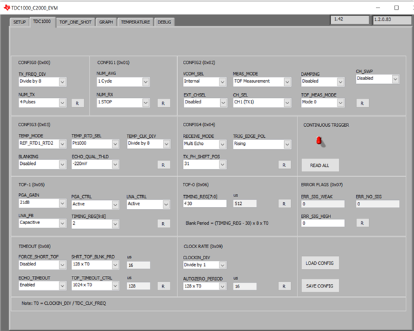
  • GUI Configuration:
    In the GUI, I have tried the following settings:

    • Clock Divider: 32
    • NUM_TX Pulse: 4
    • PGA Gain: 21 dB
  • Observed ToF:
    With the above settings, the ToF value I am seeing in the GUI is around 59 µs.

However, when I back-calculate the distance based on the ToF, the result does not match the expected distance for the 100mm acrylic box. The ToF measurement does not give the correct value, which suggests that either the setup or the configuration might not be correct.

Could anyone with experience in using the TDC1000-C2000EVM, or similar transducer setups, provide guidance or suggestions on how to troubleshoot this issue? Specifically, why might the measured ToF be incorrect and what changes should I consider to get the accurate measurement corresponding to the physical dimensions of the acrylic box?

Any help or pointers would be greatly appreciated!

  • Hello Abhijit,

    Thanks for posting to the sensors forum and for the details so far!

    Did you change the clock that is on the TDC1000-C2000EVM? The reason I ask is because the transducer you provided has a resonant frequency of 400kHz while the signal you may be providing is at 250kHz.

    The reason you keep triggering getting at a fixed ToF of 59us is probably because the timing windows have not be configured properly on the device. Meaning that the device is listening for an echo much earlier than it should be so you are probably triggering on the noise of the excitation pulse as the signal ramps down.. You can configure the correct listening window by using the expected speed of sound in the medium that you are measuring in. Here is a quick snapshot of the standard ToF mode. I included a capture of the standard ToF mode and highlighted some of the registers you would need to change the measurement periods. Keep in mind if you are using the short ToF method these registers would be different.

    Best,

    Isaac

  • Hi Lara,

    I am attaching the Standard ToF measurement configuration in the GUI. Please check whether it is correct or not.

  • I am not getting accurate result.

  • Abhijit,

    This may not be correct, mainly due to the external clock. If you did not change to the external clock option you may be generating a 1MHz pulse on a 400kHz transducer, please make sure to provide an external clock on TP19 as well as changing the setting for JP1 on the hardware. You can also enter the correct clock value on the "Setup" so that the GUI reflects the correct values. 

    Another question I have is how you are trying to make your measurement? Are you trying to make it through the top or bottom of the tank and what is your transmission medium?

    Best,

    Isaac

  • Lara,

    i am giving internal clock only and If I use clock divider as 16 then the  transducer is getting 500kHz pulse right? is it ok.

    another doubt I have replaced the transducer with a new one having resonant frequency as 1Mhz and same i am not getting accurate result.

    I have filled the acrylic box with fresh water and connected the transducer ,leftside of the box.

    Thank you.

  • Hello Abhijit, 

    That's too large of a difference for  a 400kHz transducer, so I would not expect that using a 500kHz signal would work.

    Have you followed our guide on how to mount transducers to the tank? If the transducer is not mounted properly you will not get a proper reading from the device because the signals emitted from the transducer will reflect and scatter from the tank.

    Here is a document that might help: https://www.ti.com/lit/an/snaa266a/snaa266a.pdf

    Best,

    Isaac