IWR1443BOOST: Large Discrepancy Between Theoretical and Experimental SNR Values

Part Number: IWR1443BOOST
Other Parts Discussed in Thread: DCA1000EVM, IWR1443, IWR1642BOOST

Tool/software:

Post:

Hello TI Experts,

I am working on SNR analysis for the IWR1443BOOST radar for a client and have encountered a significant gap between my theoretical and experimental SNR results. I would greatly appreciate any guidance to help resolve this issue. My method should also be applicable to other sensor modules from TI.

Theoretical SNR Calculation:

I used the following SNR equation:

SNR = (Pt * GRx * GTx * c2 * σ * N * Tr) / (fc 2 * (4π)3 * kT * NF * R4)

  • Transmit Power Pt=0.0158 (12dBm)
  • Antenna Gain Gt=Gr=7.94 (9 dB) 
  • Wavelength λ=3.797×10⁻³ (79 GHz) ( = c 2 / fc 2)
  • System Temperature T=290K
  • Noise Figure Nf=31.62 (15 dB)
  • Chirp Repetition Period Tr=3042.58×10−6 s
  • Number of Chirps per Frame N=16 (as per TI mmWave Sensing Estimator)

Experimental SNR:

  • Environment: Measurements were conducted in an anechoic chamber (for almost conditions) and noise was averaged over 10 seconds to get an averaged noise floor (at each range bin). 
  • A target with known RCS was placed at different distances and relative received power recorded at each distance.
  • using TI demo visualizer data was captured and analysed ( The configuration used was : SDK:2.1.0.4 , 2 Tx, 4 Rx,  Best Range resolution, 77-81 GHz,  10 fps, Range Resolution 0.04 m , maximum unambiguous range 7.17m.
  • SNR was measured at each distance by subtracting relative power (dB) - noise floor (dB) at each distance. 

Issue:

Despite using the anechoic chamber noise floor for ideal conditions, the experimental SNR is consistently around 25 dB lower than the theoretical SNR calculated with the equations. This gap is larger than expected and persists across the measured distances (in the far field region)

Questions:

  1. Could this discrepancy be due to additional system losses or specific processing gains not accounted for in the Demo Visualizer?
  2. Are the relative received power and noise floor outputs in the Demo Visualizer scaled in a specific way?
  3. Are there any additional calibration steps or adjustments recommended to align the theoretical and experimental SNR values?

I would greatly appreciate any insights or suggestions to help resolve this gap and ensure accurate SNR analysis for the IWR1443BOOST.

Thank you for your assistance!

  • Hello.

    Just a few follow-up questions: 

    1) Which SW are you using?

    2) What SNR are you expecting and what SNR are you seeing

    3) Have you tried using the PostProc tool as part of mmWave studio to process the data as it will produce an SNR output value for you to use in comparison with the theoretical SNR that you have computed?

  • Hello Mr. Krishnan,

    Thank you for your reply.

    1) SW Used:

    I am using the TI mmWave Demo Visualizer for data capture. I’ve developed a custom Python script for parsing UART data (that mimics Demo Visualizer output in terms of Range and Noise profiles) and then calculating SNR. I do not have access to the DCA1000EVM, so my analysis relies on the processed output from the Demo Visualizer data capture, rather than raw ADC data.

    2) SNR Comparison:

    Theoretical SNR values from equations are around 80 dB (5m distance to target), while my experimental SNR results at that distance are around 55 dB.

    3) PostProc Tool:

    Since I’m not using the DCA1000EVM -and I don't think I need it for my project- I haven’t tried the PostProc tool. Does the Demo Visualizer apply any specific scaling or calibration that could explain this discrepancy? Any suggestions for aligning the SNR results without raw ADC data would be appreciated.

    Best regards,

  • Hello.

    I am looking into this and will provide an update by the end of the day Thursday.

    Sincerely,

    Santosh

  • Hello.

    I would double check that your SNR computation matches how the SNR computation should be done with the 1443 processing chain.  Please refer to this E2E for how SNR can be computed for the detected objects list in the 1443 processing chain.

    Sincerely,

    Santosh

  • Hello Santosh,

    Thank you for your response and for providing the link to the E2E discussion.

    I have a couple of follow-up questions:

    1. I understand that IWR1443 does not directly give SNR calculation, but using PeakVal from the detected objects TLV is a recommended approach. However, I’ve been using the range profile from the Demo Visualizer in my analysis due to its availability and ease of use. The range profile provides continuous power measurements even when the target is not detected as an object by the CFAR algorithm. Could you confirm if using the range profile instead of PeakVal would lead to significant discrepancies in SNR estimation? Are there specific scaling or adjustments applied to the range profile that differ from PeakVal in the detected objects TLV?

    2. Does the method of calculating SNR using PeakVal and the noise profile apply similarly to the IWR1642BOOST board, or are there differences in the processing chain for this board that I should be aware of?

    3. The other E2E discussion mentions: (If you compare the range profile (zero doppler) and signal power of a static detection, you may have an idea whether they have the same scale. If so, then you can use the noise profile directly for SNR estimation.). How to verify whether they are using the same scale? I was under the impression they (range and noise profiles) use the same scale as they are plotted in the same plot within the demo visualizer.

    Your guidance would be greatly appreciated as I work on aligning my analysis with the recommended SNR calculation method.

    Best regards, Mashal. 

  • Hello.

    I understand that IWR1443 does not directly give SNR calculation, but using PeakVal from the detected objects TLV is a recommended approach. However, I’ve been using the range profile from the Demo Visualizer in my analysis due to its availability and ease of use. The range profile provides continuous power measurements even when the target is not detected as an object by the CFAR algorithm. Could you confirm if using the range profile instead of PeakVal would lead to significant discrepancies in SNR estimation? Are there specific scaling or adjustments applied to the range profile that differ from PeakVal in the detected objects TLV?

    It would depend on how you are using the range profile in your SNR computation.  The peakVal is computed in the data_path.c file as follows:

    obj->objOut[idx].peakVal = obj->rangeDopplerLogMagMatrix[obj->objOut[idx].rangeIdx*obj->numDopplerBins +
                    obj->objOut[idx].dopplerIdx].
    This is utilizing the range-doppler heatmap as opposed to the range profile, so it may be that this difference may be the root cause of the difference you are seeing in your SNR computation.
    • Does the method of calculating SNR using PeakVal and the noise profile apply similarly to the IWR1642BOOST board, or are there differences in the processing chain for this board that I should be aware of?

    I believe the SNR computation should remain the same for the 1642, however, since the antenna configuration is different the overall processing chain to get the detected objects will have some differences; you can refer to the SDK software for more information on the processing chain for the 1642.

    The other E2E discussion mentions: (If you compare the range profile (zero doppler) and signal power of a static detection, you may have an idea whether they have the same scale. If so, then you can use the noise profile directly for SNR estimation.). How to verify whether they are using the same scale? I was under the impression they (range and noise profiles) use the same scale as they are plotted in the same plot within the demo visualizer.

    It may be that even though they are plotted in the same graph, the scales for the data itself may be different, so you should check the zero-doppler range profile and the signal power to confirm this before you use the noise profile directly.

    Sincerely,

    Santosh

  • Dear Santosh,

    I couldn’t reply to your latest post so instead I will reply to this one.

    Thank you for your detailed response and clarifications. I now understand that PeakVal is computed using the range-Doppler heatmap, which differs from the range profile.

    I would also like to share an additional observation:

    • I analyzed another data file captured without any target present, where the range profile and noise profile appeared similar in the Demo Visualizer plot. Printing the values in the captured .dat file confirmed that the range profile and the noise profile are in the same scale in this scenario.
    • However, when a static target is present, I observed significant differences between the PeakVal (from the detected objects TLV) and the range profile values at the corresponding range bin. This suggests that PeakVal and the range profile may use different scales or undergo different processing.

    Could you provide more clarity on:

    • How the PeakVal is scaled compared to the range profile and noise profile?
    • Which one (PeakVal or Range profile) will be more representative of received power from a stationary corner reflector experiment?
    • Whether the range profile (zero Doppler) and noise profile being on the same scale in scenarios without a target is sufficient to justify using the range profile for SNR estimation as my experiments involve stationary objects anyway, and -if my method of calculating SNR by subtracting (Range profile – average noise profile) is sound- how can we explain the large discrepancy in SNR between theoretical and experimental.

     Thank you again for your assistance, and I look forward to your insights.

    Best regards,
    Mashal

  • Hello.

    How the PeakVal is scaled compared to the range profile and noise profile?

    After looking through the code, I believe the peakVal, range profile, and noise profile should all be scaled in dB since they use the rangeDopplerLogMatrix which contains the log magnitudes for the range-doppler heatmap.

    Which one (PeakVal or Range profile) will be more representative of received power from a stationary corner reflector experiment?

    I would suggest using the peakVal for the relative signal strength of the detected object.  I assume you are just using the value of the range profile at the specific bin where the corner reflector is sitting at, but the peakVal also takes into account the doppler index as well.

    Whether the range profile (zero Doppler) and noise profile being on the same scale in scenarios without a target is sufficient to justify using the range profile for SNR estimation as my experiments involve stationary objects anyway, and -if my method of calculating SNR by subtracting (Range profile – average noise profile) is sound- how can we explain the large discrepancy in SNR between theoretical and experimental.

    I'm not sure where you are getting this assumption from as the prior E2E only mentions the comparison between the range profile and noise profile being on the same scale to justify using the noise profile in the SNR computation.

    Sincerely,

    Santosh

  • Dear Santosh,

    Thank you for your detailed response and recommendations. I appreciate the time you spend answering my posts, and I believe this discussion can be helpful for the wider community. Many thanks.

    I’d like to clarify the original issue with my SNR experiments involving a stationary corner reflector. While the shape of my experimental SNR graph matches the theoretical one, there is a consistent discrepancy of around 25 dB. This suggests a potential linear scaling factor affecting the results and that's what I am trying to identify here. 

    Furthermore, based on the other post you shared informing that noise profile can be considered as the average thermal noise, I modified my theoretical calculation to only account for thermal noise, but this approach resulted in an even bigger discrepancy. 

    Could you help clarify:

    1. Whether there are additional noise factors or scaling corrections applied to the range and noise profiles that could explain this discrepancy? For example integration gain or Time-Bandwidth product.
    2. Can range and noise profiles still provide an accurate Signal-to-Thermal Noise Ratio, or do they include other noise sources beyond thermal noise? 

    Thank you for your support, and I look forward to your insights.

    Best regards,
    Mashal

  • Hello.

    Whether there are additional noise factors or scaling corrections applied to the range and noise profiles that could explain this discrepancy? For example integration gain or Time-Bandwidth product.

    That post emphasizes that the noise profile that is computed is like the thermal noise profile and does not account for the environment clutter.  This environmental clutter could be the reason you are seeing the discrepancy.  

    Can range and noise profiles still provide an accurate Signal-to-Thermal Noise Ratio, or do they include other noise sources beyond thermal noise? 

    Again, as I stated before and as is stated in the linked E2E, I would recommend that you use the peakVal as opposed to the range profile for SNR estimation and the noise profile is ok to use if the signal strength of the static detection and the range profile are close to each other.  However, the noise profile does not include the environmental clutter and so if you care about the Signal-to-Thermal Noise ratio you can use this noise profile.  You can get this peakVal value from the detected objects list that is sent from the device to the visualizer over UART.

    Sincerely,

    Santosh

  • As an update, I would like to note that if you are doing this SNR computation on a static object, you can use the noise profile and use the peak of the zero-doppler range profile instead of the peakVal value that comes off the device.  However, if the object is moving, you will not know which range profile at what doppler index to use to find the signal strength for that moving detected object, hence why it is recommended to use the peakVal that is transmitted from the device via UART with each detected object.

  • Dear Santosh,

    Thank you for your detailed response. I understand that for stationary objects, it makes sense to use the range profile since it should remain close to the peakVal. However, from my observations, the two values do not match at the same range bin, which raises some questions.

    While environmental clutter may account for some of the SNR discrepancy, the uniform nature of the observed gap suggests it is more likely due to a scaling factor.

    I learned a lot from this discussion and I think we are almost touching the point. I would appreciate your guidance on addressing this matter or if you could suggest an alternative method for accurately estimating SNR in this scenario. 

    Best regards,
    Mashal Bimani

  • Dear Santosh,

    I wanted to provide an update and clarify my earlier observation regarding the mismatch between the PeakVal and the range profile at the same range bin. Specifically:

    1. I scaled the range profile value at the range bin using the scaling equation provided in the demo visualizer's JSON source file:

      if (Params.rangeProfileLogScale == false) {
      math.forEach(rp, function (value, idx, ary) {
      ary[idx] = Params.dspFftScaleCompAll_lin[subFrameNum] * Math.pow(2, value * Params.log2linScale[subFrameNum]);
      });
      } else {
      math.forEach(rp, function (value, idx, ary) {
      ary[idx] = value * Params.log2linScale[subFrameNum] * Params.toDB + Params.dspFftScaleCompAll_log[subFrameNum];
      });

      This method successfully reproduces the values displayed in the demo visualizer's range profile plot.

    2. I converted the PeakVal to dB using the formula:

      PeakVal to dB = 10 * log10(PeakVal)

    An example to clarify further, in the case of a stationary target at ~3 meters:

    • Number of Detected Objects: 1
    • xyzQFormat: 512
    • Detected Object 0:
      • RangeIdx: 87
      • DopplerIdx: 0
      • PeakVal: 3238
      • Coordinates: (0.0, 3.072265625, 0.0)
    • Converted PeakVal to dB: 35.1 dB

    Range Profile Value at RangeIdx 87: 10592

    • Scaled to dB (using demo visualizer method): 106.49 dB

    This shows a significant discrepancy between the scaled range profile value and the converted PeakVal, even for stationary objects.

    Could you help clarify if additional scaling or corrections might be applied to the PeakVal in the demo visualizer or in the radar's firmware? This difference is consistent across tests and appears unlikely to be caused by environmental noise or clutter.

    Thank you again for your insights and suggestions.

    Best regards,
    Mashal

  • Hello Mashal.

    peakVal should already be in dB when it is sent from the device, but let me double check the computation and provide an update by end of day Tuesday of next week.  I also understand you are using the values from the visualizer, and so let me check what the data is being saved as(as to whether it is linear or dB, the processing chain seems to indicate the range profile as an array of log magnitude values).  Have you tried just read the UART data and is that where you are getting the detected object information from?

    Sincerely,

    Santosh

  • Dear Santosh,

    Thank you for your response. Regarding your comment:

    1. Range Profile: Based on my analysis of the demo visualizer's JSON code, the range profile values sent over UART are in linear format and then scaled to dB in the visualizer using the formula:

      ary[idx] = value * Params.log2linScale[subFrameNum] * Params.toDB + Params.dspFftScaleCompAll_log[subFrameNum];

      I have confirmed that applying this scaling exactly matches the visualizer's output.

    2. PeakVal: Similarly, from the JSON processing logic, peakVal is extracted in linear form and converted to dB using:

      10 * log10(peakVal).

      Also confirmed with this E2E post: e2e.ti.com/.../awr1642-covert-peakval-from-linear-to-db

    To answer your question, I am extracting all data (range profile, noise profile, and peakVal within detected objects TVL) directly from the UART. You can also refer to the example values I shared in my previous post. 
    Thanks again for your time and I am looking forward to receiving your feedback. 

    Sincerely,
    Mashal

  • Hello Mashal.

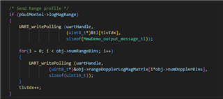
    One more question I had; when the demo is sending the range profile information over UART, it sends the range profile for every doppler index as opposed to just the one with the detected object.  Can you confirm that you are checking the correct range-profile(in this case I would assume the zero-doppler doppler-index)?  The peakVal is extracted from the same matrix that is sent out for range-profile so the mismatch in values indicate you might be using the wrong range profile.

    How range profile is sent from device over UART

    How peakVal is computed

  • Hello Santosh,

    Thank you for the clarification and the attached code snippets. Based on the implementation, I understand that:

    1. The range profile represents the zero-Doppler slice of the rangeDopplerLogMagMatrix across all range bins, as indicated by the UART transmission logic. I also noticed that the demo visualizer explicitly labels the range profile plot as "Range Profile for Zero Doppler," which suggests the range profile corresponds to the zero-Doppler index.
    2. The peakVal is extracted at the specific (rangeIdx, dopplerIdx) location in the same matrix, making it highly dependent on the detected object’s Doppler index.

    For stationary targets (zero Doppler), the peakVal and the zero-Doppler range profile value at the same rangeIdx should align more closely. However, I’m still observing a significant discrepancy between the two in my experiments. This raises questions about potential scaling differences or additional processing steps.

    Also, I’d like to remind you that my original question regarding the consistent ~25 dB discrepancy in SNR calculations (theoretical vs experimental) is still unresolved. I’d appreciate your guidance on that as well.

    Best regards,
    Mashal

  • Hello.

    For stationary targets (zero Doppler), the peakVal and the zero-Doppler range profile value at the same rangeIdx should align more closely. However, I’m still observing a significant discrepancy between the two in my experiments. This raises questions about potential scaling differences or additional processing steps.

    Understood, just wanted to confirm this as the UART data from the device seems to get processed by the visualizer so I wasn't sure how they related.  Let me look into this and provide an update by the beginning of next week due to Thanksgiving holidays.

    Also, I’d like to remind you that my original question regarding the consistent ~25 dB discrepancy in SNR calculations (theoretical vs experimental) is still unresolved. I’d appreciate your guidance on that as well.

    Did you try doing the SNR computation with the peakVal as opposed to the range profile?  I recall you saying you took into account the noiseProfile differences but I did not recall if you had tried the computation again with the peakVal.  But also given that the peakVal and the range profile value are not close(35.1 dB to 106 dB), using only the noise profile may be why you are seeing the discrepancy.

    noise profile is ok to use if the signal strength of the static detection and the range profile are close to each other.

    Also, it looks like the peakVal is computed using 10log10(peakVal) but the rangeProfile uses 20log10(rangeProfile), but you can use 20Log10 for peakVal to get relative power as stated in this e2e; that might account for the difference in rangeProfile and peakVal values.

    Sincerely,

    Santosh

  • Dear Santosh,

    Thank you for your detailed response and clarification regarding the peakVal and range profile computations.

    1. SNR Discrepancy Update:
      After revisiting my calculations, I found that using the correct chirp time (Tchirp) instead of the repetition period (Tr) for the theoretical noise power and also using the correct scaling as detailed in the Demo Visualizer’s JSON source file has reduced the SNR gap to ~6 dB in the far field. This significantly improved from the ~25 dB gap I initially reported. However, this remaining 6 dB discrepancy raises further questions:
      • Could this be attributed to unaccounted system losses, such as signal processing losses, resistive losses, or coupling losses, which are not included in the noise figure?
      • How confident can we be about the antenna gain figures provided in the datasheet? Do they include the effects of beamforming? with 4 receivers, there should be ~6 dB gain through beamforming? Could this gain be missing or misrepresented in the theoretical model?
    2. PeakVal vs. Range Profile for SNR:
      I have attempted SNR calculations using both the range profile and the peakVal for stationary targets. The scaled peakVal remains significantly lower than the range profile value at the same rangeIdx (e.g., ~35.1 dB for peakVal vs. ~106 dB for range profile). Even after using 20log10 (peakVal becomes ~70.2 dB), Furthermore, my handling of the range profile exactly matches what is displayed in the Demo Visualizer which gives me confidence in my calculations, unless what is displayed in the demo visualizer is not significant. Having the gap down to ~6dB is encouraging that my methods are likely valid (using range profile relative - average noise floor to get SNR)

    Thank you for your continued guidance, and I look forward to your insights on these questions after the Thanksgiving holidays.

    Best regards,
    Mashal

  • Hello Mashal.

    • Could this be attributed to unaccounted system losses, such as signal processing losses, resistive losses, or coupling losses, which are not included in the noise figure?
    • How confident can we be about the antenna gain figures provided in the datasheet? Do they include the effects of beamforming? with 4 receivers, there should be ~6 dB gain through beamforming? Could this gain be missing or misrepresented in the theoretical model?

    This discrepancy can definitely be attributed to unaccounted system losses and also because that it will not match the theoretical exactly due to the environmental parameters that could influence the actual results.  You can be confident in the antenna gain values in the datasheet, but they are for the base antenna configuration and do not account for beamforming as that would increase the antenna gain then under normal chirping operation.

    I have attempted SNR calculations using both the range profile and the peakVal for stationary targets. The scaled peakVal remains significantly lower than the range profile value at the same rangeIdx (e.g., ~35.1 dB for peakVal vs. ~106 dB for range profile). Even after using 20log10 (peakVal becomes ~70.2 dB), Furthermore, my handling of the range profile exactly matches what is displayed in the Demo Visualizer which gives me confidence in my calculations, unless what is displayed in the demo visualizer is not significant. Having the gap down to ~6dB is encouraging that my methods are likely valid (using range profile relative - average noise floor to get SNR)

    I am definitely surprised that this is the case, you are correct in being able to use the range profile in this case due to the object being static, I will look into why this discrepancy exists and provide an update by EOD Monday of next week.  Thank you for your patience.

    Sincerely,

    Santosh

  • Dear Santosh

    Any updates regarding the above two issues?

    Sincerely,

    Mashal 

  • Hello Mashal.

    This discrepancy can definitely be attributed to unaccounted system losses and also because that it will not match the theoretical exactly due to the environmental parameters that could influence the actual results.  You can be confident in the antenna gain values in the datasheet, but they are for the base antenna configuration and do not account for beamforming as that would increase the antenna gain then under normal chirping operation.

    This was my response for the first issue.

    I am definitely surprised that this is the case, you are correct in being able to use the range profile in this case due to the object being static, I will look into why this discrepancy exists and provide an update by EOD Monday of next week.  Thank you for your patience.

    And apologies for the delay in response, I am still looking into this issue and will provide an update by the end of the week.

    Sincerely,

    Santosh

  • Hello Mashal.

    For the peakVal, can you try scaling it the same way the range profile is being scaled or vice versa?  When I do 20log10(10592), which is the value from the range profile that you provided, i found that it is around 80 dB, and if you did 10log10 it is around 40 dB, while the peakVal is around 70 dB and 35 dB, respectively.  This might indicate that you might be scaling your values in two distinct ways, which may be causing the discrepancies you are seeing.  I am still looking into why the actual values are different since in the SW they are pulled from the same matrix, but please try using a consistent scaling when calculating your values.

    Sincerely,

    Santosh

  • Dear Santosh,

    Thank you for your suggestion. I tried scaling PeakVal like the range profile and vice versa, however the scaled values remain inconsistent. I have tried across multiple examples from different experiments. The next table shows some examples:

    RangeIdx PeakVal RangeProfile PeakVal (Log) PeakVal (Scaled Like RangeProfile) RangeProfile (Scaled same ad Demo Visualizer) RangeProfile (Log)
    87 3238 10592 70.21 20.01 106.49 80.50
    144 1204 9848 61.61 -3.90 97.74 79.87
    79 1930 10192 65.71 4.63 101.79 80.17
    2 277 8768 48.85 -14.80 85.04 78.86
    56 483 9184 53.68 -12.38 89.93 79.26
    79 1128 9792 61.05 -4.80 97.08 79.82
    2 278 8776 48.88 -14.79 85.14 78.87

    I appreciate your guidance and support to resolve this discrepancy.

    and Regarding the 6 dB SNR difference, can you confirm I can assume a 6 dB gain through beamforming since there are 4 receivers? 

    Best regards
    Mashal 

  • Hello.

    I believe all the values that come off the device are in a Q9 format, so you would need to divide all the values by 512 before doing any of your scaling.  One thing I would like to confirm is that have you checked the range profile that is streamed directly off the UART?  Or are you looking at the range profile from the visualizer?  There may be some summation or extra computation done to plot the range profile values so instead I would look at the first rangeDopplerLogMagMatrix array that is streamed out as part of the range profile TLV and compare the value of that index to the stationary object's peakVal.

    and Regarding the 6 dB SNR difference, can you confirm I can assume a 6 dB gain through beamforming since there are 4 receivers? 

    This is more likely due to approximations and scalings in the computation that can result in differences between the theoretical computation and the experimental results.  Beamforming is not done as part of this demo.

    Sincerely,

    Santosh

  • Dear Santosh,

    Thank you for your clarification. I have applied Q9 scaling by dividing values (e.g., PeakVal and range profile) by 512 before applying any scaling. However, the discrepancy between PeakVal and range profile values for stationary objects persists.

    Regarding the range profile, my code directly parses the rangeDopplerLogMagMatrix array from the range profile TLV streamed directly via UART. I think the range profile values I am working with match the expected data structure from the SDK, and match the ones shown in Demo Visualizer confirming that I am analyzing them the right way. 

    For the 6 dB SNR difference, I understand this is likely due to approximations and scalings in the computation rather than beamforming. However, since 6 dB corresponds to a factor of 4 in power, could you provide more details on the specific approximations or scalings that could result in this discrepancy? Additionally, since beamforming is not implemented in the demo, are amplitude and SNR values based on independent receiver outputs, or are they combined in some other way? (I am using 4 Rx antennas in my experiments) 

    Thank you for your continued guidance and support.

    Best regards,
    Mashal

  • Hello.

    For the 6 dB SNR difference, I understand this is likely due to approximations and scalings in the computation rather than beamforming. However, since 6 dB corresponds to a factor of 4 in power, could you provide more details on the specific approximations or scalings that could result in this discrepancy?

    As we discussed earlier, the noise that you are using is also an approximation, so this combined with any scaling done in the SW and summations when computing the range profile can result in some inaccuracies.  However, I misunderstood beamforming to be Tx beamforming, but Rx Beamforming could also result in an increased gain.

    Regarding the range profile, my code directly parses the rangeDopplerLogMagMatrix array from the range profile TLV streamed directly via UART. I think the range profile values I am working with match the expected data structure from the SDK, and match the ones shown in Demo Visualizer confirming that I am analyzing them the right way. 

    One thing to note is that the peakVal is obtained after doing the full processing chain(range, doppler, and angle) and so this could result in a different value than the highest magnitude in the zero-doppler range profile.  But one thing you could check is to see if the difference in value is in the SW itself as opposed to what is processed by you.  I would print out the peakVal and the magnitudes in the matrix to see if any of the values match, and it might indicate whether this is an appropriate comparison to make.  Between I would just use which ever value results in the SNR closest to your expected value.

    Sincerely,

    Santosh.

  • Dear Santosh,

    Thank you for clarifying the role of Rx beamforming. Could you confirm whether Rx beamforming is applied in the demo software? If so, should I incorporate the 6 dB gain into the theoretical calculations, and is it already included in the range profile profile values?

    Additionally, are there any quantified losses (e.g., scaling, summations, or approximations) that I could include in my theoretical calculations to better align with experimental results?

    Regarding PeakVal, I appreciate the explanation. I will continue to use the range profile for consistency.

    Best regards,
    Mashal

  • Hello.

    Could you confirm whether Rx beamforming is applied in the demo software? If so, should I incorporate the 6 dB gain into the theoretical calculations, and is it already included in the range profile profile values?

    Beamforming is enabled if you set the flag in the demo to do so.  6 dB is not a constant used anywhere in the demo, so I would account for this difference experimentally as opposed to factoring in your theoretical calculations.

    Additionally, are there any quantified losses (e.g., scaling, summations, or approximations) that I could include in my theoretical calculations to better align with experimental results?

    I don't think that is something available since it depends on a multitude of factors including the environment so you would have to take measurements to get better information on these losses.  You can also refer to the demo software code to see what calculations are being done and extract what you can from those processes as well.

    Sincerely,

    Santosh

  • Dear Santosh,
    Thank you for your detailed response. Your insights are extremely helpful as I work to align my experimental results with theoretical calculations. However, I have a couple of follow-up questions :

    Beamforming Settings:
    I am unclear where the beamforming flag or setting can be controlled in the demo software. Could you guide me on where this option is configured? Specifically, I would like to confirm whether beamforming was enabled during my experiments or if I need to explicitly enable it for future tests.

    Quantifying Experimental Losses:
    I understand from your response that losses due to scaling, summations, and environmental factors are not predefined and must be experimentally validated. However, without a theoretical reference or documented information in the radar datasheet, I find it challenging to isolate and quantify these losses. Could you suggest a methodology or best practices for experimentally estimating these losses?

  • Beamforming Settings:
    I am unclear where the beamforming flag or setting can be controlled in the demo software. Could you guide me on where this option is configured? Specifically, I would like to confirm whether beamforming was enabled during my experiments or if I need to explicitly enable it for future tests.

    There is a CLI command that looks like it enables/disables this(multiObjBeamForming).  Please refer to the configuration files for setting this.

    I understand from your response that losses due to scaling, summations, and environmental factors are not predefined and must be experimentally validated. However, without a theoretical reference or documented information in the radar datasheet, I find it challenging to isolate and quantify these losses. Could you suggest a methodology or best practices for experimentally estimating these losses?

    Unfortunately, you will have to look into this, a few things I can recommend is first calculating the losses in a clear environment by using a fixed target in a no clutter environment as a starting point.

    Sincerely,

    Santosh