- Ask a related questionWhat is a related question?A related question is a question created from another question. When the related question is created, it will be automatically linked to the original question.
This thread has been locked.
If you have a related question, please click the "Ask a related question" button in the top right corner. The newly created question will be automatically linked to this question.
Tool/software:
TI Team,
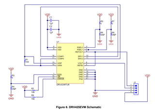
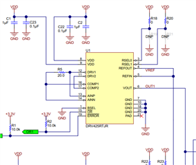
What is the difference between the schematics from Figure 1 DRV425EVM and Figure 2 from TIDA 00463.
In figure 1, The shunt resistor is on the trace bewteen DRV2 (Pin 11) and COMP2 (Pin 17)
In figure 2, The shunt resistor is on the trace bewteen DRV1 (Pin 12) and COMP1 (Pin 16)
How does it impact the design? Is there a specific reason for this config? Does it affect the measurement or sensitivity?

Figure 1 - DRV425EVM

Figure 2
Hello Sid,
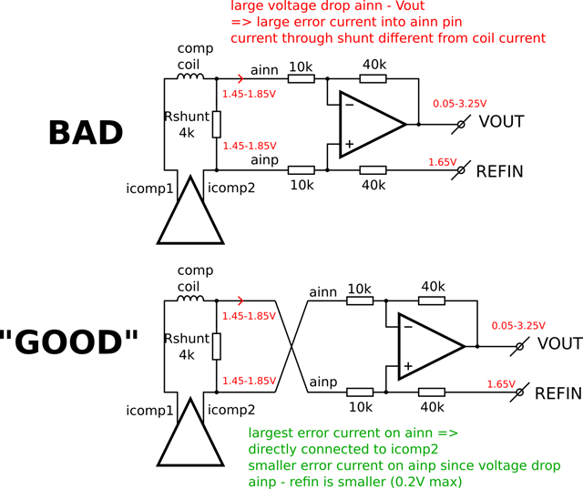
It does not impact design as it is a shunt resistor used to measure current along the path. There is no specific reason for this other configuration. If you use a large Rshunt >500Ω I would just recommend that the AINN be connected to the ICOMP pin to limit input bias current changes across the Rshunt. The reason shown below. The two examples above have it connected correctly.
