This thread has been locked.

If you have a related question, please click the "Ask a related question" button in the top right corner. The newly created question will be automatically linked to this question.

TDC1000-C2000EVM: NOT RECEIVING ECHO PULSE WITH THE HV CIRCUIT

Part Number: TDC1000-C2000EVM

Tool/software:

Hello.

This was our previous thread (here), we appreciate the responses given.

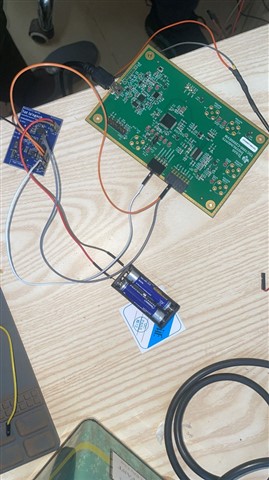
We have made significant progress in our application. We tested the EVM with plastic bottles and 3mm thick steel metals and we were able to get accurate results.

We tested the EVM with an LPG cylinder and the signals were not able to penetrate it.

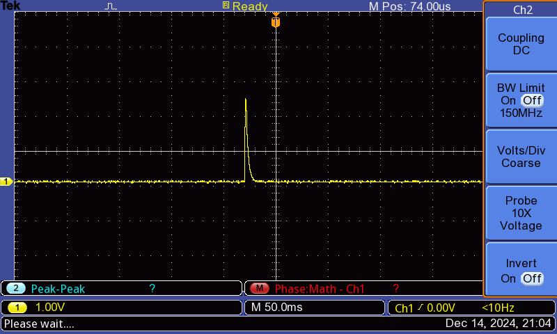
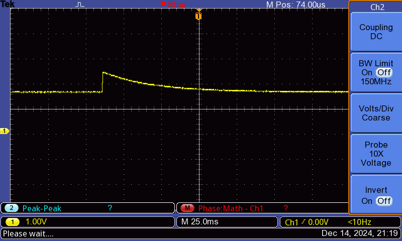
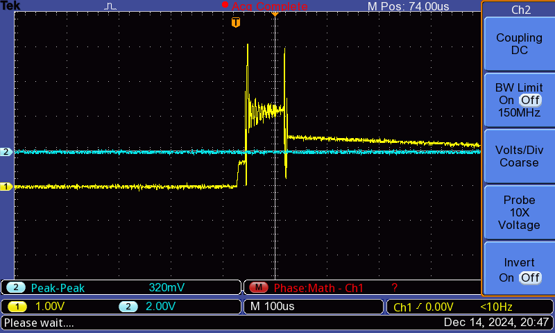
We developed an HV board based on the reference given (here) to boost the voltage and although the HV TX pin indicated the 30 V as expected (shown in the scope image), we were unable to receive the echo pulse.

With the GUI, we enabled the TDC1000-HV Driver EN1 after connecting the EVM to the HV circuit board.

With the same GUI settings, we receive an echo signal without the HV circuit board, but we don't receive it when use the HV circuit.

Do you have any advice on what to do to receive the echo signal? 


  • Hello Semyalo,

    Thanks for posting to the sensors forum! I am guessing the capture here is for the TX pulse, it definitely looks like a larger voltage, but can you zoom in to verify that the frequency is appropriate?

    For the return echo can you probe the COMPIN pin, you also need to make sure that the echo listening window is configured appropriately, for now you can make it as large as possible just to ensure that we are just capturing the echo.

    Best,

    Isaac 

  • Hello Isaac,

    Here are the settings we had. We set a really high listening window 

    When we zoomed in to the Tx pulses, this is what we observed. Our Transducer is 1MHz.

    We did some additional testing to identify where the signal gets lost along the received signal path (LNAOUT (R21), PGAOUT (R27), and at R30 which connects the COMPIN)

    The images below are shown in that order (

    LNAOUT (R21)

     PGAOUT (R27)

     COMPIN (R30)

    When we disconnected the HV, and tested the transducer without it, this is the signal at R30, which gives good results.

    What adjustments can we do to make sure that we get an echo signal when we use the HV?

  • Semyalo,

    Can you try increasing the amount of pulses you are sending out and capture the waveform so that I can see what the signal looks like?

    Also I am not sure if your transducer is receiving any data. The LNA and PGA signals dont look like how we would expect them to look whenever they are getting data so my assumption would be that they are somehow now connected. 

    A good way to test out your RX and TX is to test it out with another system and check if you are sending out data correctly as well as receiving data from the other system. My first thought is that perhaps the TX is not generating the pulses appropriately so if this is not sending out the transmission at the correct frequency this would explain why you are not getting anything back during the listening period. If you are transmitting properly then perhaps there is something that needs to be addressed on the RX portion.

    Best,

    Isaac

  • Hello Isaac,

    We managed to generate pulses on Tx with our 1Mhz transducer we have been using playing around with the settings (image below).

    The HV Circuit recommended hasn't been useful so far, so we tried it without HV on Tx, and received some good results for our 6kg (22cm high) LPG cylinder.

    However, we can't be able to receive echo in a larger (130cm high) LPG cylinder. We are thinking of using a lower value transducer e.g. 500khz, 200khz

    due to a significant difference in sound travel between water and our liquified gas.

    We realised that the interstage filters on the EVM is set to a 1mhz. Could you please recommend the values we can change at this filter so as to accommodate less than 1mhz frequency? 

    Otherwise if you have any other recommendation on how to achieve this would be of much help.

    Regards,

    Semyalo

  • Hello Semyalo,

    Thanks for the patience here. A lower frequency would help as this is able to carry more energy than the higher frequency transducers the only downside is that your measurement resolution will be reduced in comparison to the higher frequency transducer.

    I think changing the 51pF capacitors here to a higher capcitance will move the cutoff frequency to prevent the lower frequency signals from being attenuated. I would try something around the 150pF range for C10 and C20 above. The C15 capacitor is just a DC blocking cap so this one can probably remain the same. If its attenuating your signal try increasing it.

    Best,

    Isaac

  • Thank you, Isaac

    Our lower frequency transducers are to arrive this week.

    We shall be letting you know about the progress once tested.

    Regards,

    Semyalo

  • Thanks for the update Semyalo!

    Let me know if there are any other questions in the meantime.

    Best,

    Isaac

  • Hello Isaac,

    We have tested out the 500khz transducer (PSC500K018060H2AD2-B1) from Jiakang. We have also changed the hardware as advised, but looks like we can't have a signal get through the metallic cylinder. (we have tested it on a 22cm high metallic LPG cylinder)

    Below are our settings and scope image

    blue is Compin/echo, yellow is STOP pulse. Our target should be 446us

    Any more advice will be much appreciated!

    Regards,

    Semyalo

  • Hello Semyalo,

    The scope shot is a little too zoomed out can you try to zoom into the compin signal so that I can see what is going on?

    It would also be good to know what the time divisions on your scope are set to.

    Best,

    Isaac