This thread has been locked.

If you have a related question, please click the "Ask a related question" button in the top right corner. The newly created question will be automatically linked to this question.

IWR6843: dynamicFlag of cfar config

Part Number: IWR6843

Tool/software:

Dear TI experts,

I am trying to work out a better cfar config for indoor applications and found there is a flag called dynamicFlag of the People Counting project. According constants defined in RADARDEMO_detectionCFAR.c  and code in 

RADARDEMO_detectionCFAR_dynamic

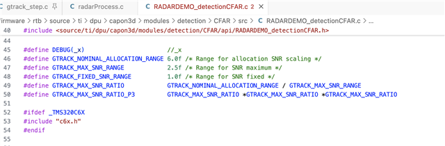
It uses a a constant threshold before GTRACK_FIXED_SNR_RANGE, this is fine. But why it's uses a linear INCREASE before reaching GTRACK_MAX_SNR_RANGE. Would you please help me understand why it's an increase slop rather than a down slop, like  the line after GTRACK_MAX_SNR_RANGE in the following plot:

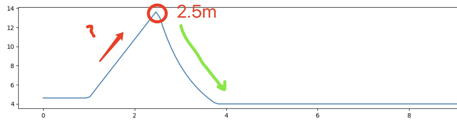
Does not it require smaller snr for longer distance if we want to detect an object? Would you please give more details about how to configure the constants use the first picture? Thanks

Best regards,

Guolong

  • Hello Guolong,

    You are correct with your statement that at longer distances, we want to be more inclusive with our SNR threshold as naturally the same object will have a higher SNR at close range as opposed to far. This linear rising edge and parabolic falling edge was designed before the inclusion of the dynamic CFAR thresholding portion, and was done so for what I believe at the time was the best behavior seen when simulated with raw data. Nevertheless, when the dynamic flag is enabled with either a value of “2” or “3”, the ratio will be multiplied by a function which simulates the magnitude of the radar signal over range. You should be looking at DPU_radarProcess_process within radarProcess.c of the capon3d folder within the dpu folder of the Radar Toolbox's source section. There you can see exactly what is being called for the 3D people tracking demo.

    Best Regards,

    Pedrhom

  • Hi Pedrhom,

    Thanks for your explanation. I am still confusing the design of linear rising edge, is it just a conclusion of simulation or based on a theory? Would you please share the mounting location when you collected the raw data?  

    Best wishes,

    Guolong

  • Hello Guolong,

    It was the conclusion based on simulation in MATLAB at the time using captured raw data. Raw data which is unfiltered, unprocessed, dumped ADC buffer data was captured and can only be captured using a DCA1000. We do not share our raw datasets nor MATLAB processing scripts publicly, but you are able to purchase a DCA1000 to collect raw data of your own to do processing algorithm development of your own.

    https://e2e.ti.com/support/sensors-group/sensors/f/sensors-forum/1441304/faq-dca1000evm-support-tools-debugging-and-more

    Best Regards,

    Pedrhom

  • Hi Pedrhom,

    Thanks for your support.

    Best wishes,

    Guolong