Tool/software:
Hi TI Experter
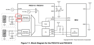
We are using FDC 2112/2212 to design the proximity sensor. I compared the characters FDC 1004 and FDC 2112. I found that FDC 1004 had the active shield pin for the shield. But, FDC 2112 do not have. Do you have the suggestion about the shield?
Thanks
Dengkuan,
Just so you know, we recommend the FDC1004 over the FDC2x1y devices due to the FDC1004 built-in active shield drivers.
Customers have struggled to get to production with the FDC2x1y devices due to EMC.
We have no reference designs for external shield drivers with the FDC2xqy devices.
Any driver amps for this function need top have high bandwidth and be able to drive large capacitances.
If I had to recommend a device to evaluate for this function, it would be the BUF602.
It is a high BW unity-gain buffer that can drive relatively large capacitances.
Regards,
John
Thanks John,
Do you have some suggestions about which position to add the circuit of BUF602? I highlighted the pin. Is it possible to add the circuit of BUF 602 to one of the pins?
Dengkuan,
That's a great question.
I hadn't completely thought this through when I made the recommendation, but each sensor pin supports half of the overall sensor waveform.
The INxA pin supports one half-cycle of the sinusoid, and the INxB pin supports the other half cycle.
The shield driver circuit will need to support the composite waveform that shows up differentially across the sensor, which is a full sinusoid centered at zero volts.
So, a buffer device will be needed each pin, and both buffer outputs will need to be connected to the shield.
As I write this, its clear there are some details to work out via prototyping, but I think this would be the best approach.
regards,
John
Hello John,
Thanks very much for your help. I'm working together with Dengkuan. Now we're trying to add the BUF602 into the design, is there anything to take care in PCB layout?
I noticed that, in the EVM design, GND around the output sensor LC tank trace has been cleared, as shown below.
I'm wondering where to locate the BUF602 circuit, is it OK to put BUF602 a little bit far away from the LC tank, due to LC tank output trace need to keep as short as possible, as suggested in FDC2x1y datasheet.
How to deal with the GND signals, which is needed for BUF602 and its peripheral circuit?
Does BUF602 also need to clear all GND as shown above?
Regards,
Danny
Danny,
The general approach for or EVMs is to clear grounds away from the built-in sensors to minimize parasitics.
This works for our EVMs because we don't need to consider mechanical and packaging requirements of a surrounding system, but that usually doesn't work for a real piece of equipment.
So our EVM layout did not consider the use of active shields, so the additional grounds and other traces will need to be added to support that feature.
In general you should keep the LCC tank traces as short as possible. It is probably okay to move the BUF602 a little further away from the LC tank. The main care-about for the active shield is that its waveform on the shield should be synchronized in amplitude and phase to the sensor waveform. For these frequencies, slightly longer BUF traces should be okay, but be careful to manage transmission-line effects to minimize any additional filter/frequency-shaping.
Also consider that you will probably need some series resistance between the BUF outputs and the shield for stability purposes, and this can introduce some low-pass frequency roll-off.
The BUF devices are very high speed amps, so they can be sensitive to their signal path parasitics, ground planes and VCC lines.
One approach might be to use their EVMs and ref designs for guidance on the best layout practices and then add these to the FDC EVM.
Please let me know if you have any questions.
Regards,
John