This thread has been locked.

If you have a related question, please click the "Ask a related question" button in the top right corner. The newly created question will be automatically linked to this question.

HDC3021: Humidity and Temp Data response time.

Part Number: HDC3021

Tool/software:

Hello,

The following are the images for your references.

While testing the current circuit, the response time of the temperature and humidity is 50 seconds but in the datasheet of the HDC3021 it shows 4 seconds.


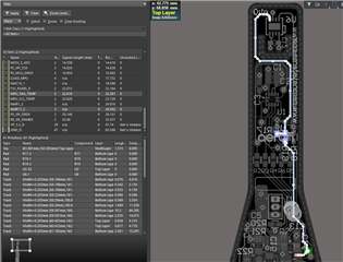
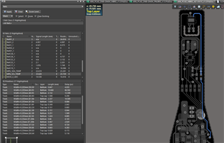
The images shows the track from sensor to Microcontroller, for SCL and SDA line 

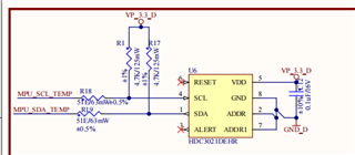
The above is the Schematic diagram the SCL and SDA line connected to the microcontroller.

I am not shielding the sensor with any material, currently testing an open PCB without covering the sensor, by comparing other comparative product the response time is very higher.

The teste is doing in the chamber, we suddenly place the sensor from ambient temperature to -40 degree. so the result is it shows the response time 50 sec to reach its 90% of reading. 

Why so? do I need to modify the schematic or any layout change?

I had followed the layout guidelines and silicon user guide for the storage as well as assembly. 

Let me know if any other input required from my end.

  • Sagar,

    Thanks for providing detail on your PCB and schematic, I think you have done the design very well and I do not recommend any changes.

    I want to first clarify our spec table for response time. For RH response time, we are claiming a 4 second 63% response time from 10% to 90% RH. This was done at room temperature, 25°C. The "63% time" means that from the 10% starting point to the 90% end point, it took 4 seconds to achieve 63% of that rise. To fully rise in humidity from 10% to the complete 90%, it does take much longer (10's of seconds).

    I'm confused about your test. You say you are going from ambient to -40°C, yet indicated temperature response, but reference the 4 second RH response time. 

    The temperature response time we spec in our datasheet is collected from 25°C to 75°C in stirred liquid, meaning an oil bath (2 seconds for a 63% response time). This is so fast because the oil is directly contacting and enveloping the full package body to allow for very fast thermal energy transfer. When doing temperature response in a chamber with air, moving or still, temperature response will be much slower.

    Depending on how you are calculating the response time (63% vs when the final value is achieved), the PCB materials, the PCB layout, moving or still air, and the temperatures chosen, 50 seconds could be a very reasonable result.

    Regards

    -Alex Thompson

  • Hello Alex,

    Thanks for the reply,

    For Image 2 the datasheet mentioned for the PCB is  Roger's 4350B material for 70.00 micron copper finish and PCB thickness 1.575mm.

    And we fabricate our PCB with FR4 material - 35 Micron(Cu/Oz)  PCB thickness is 1.6mm. So that will make the difference in the response time?

    I don't think so that will affect the more difference, but still need to find the solutions in many ways.

    So kindly check once and let me know if any solutions.

    Or suggest alternate with same specification with less response time.

  • Sagar,

    FR4 PCB with the same thickness and layout would have a marginal difference on the RH response time, perhaps it would be very slightly faster. What is critical for RH response time is the PCB thickness. For example, RH response time would be faster on a flex PCB than either FR4 or Rogers material. So I would consider the difference negligible. You should proceed as planned with FR4.

    Thanks

    -Alex Thompson