This thread has been locked.

If you have a related question, please click the "Ask a related question" button in the top right corner. The newly created question will be automatically linked to this question.

AWRL6432: TrueGroundSpeed Offline Processing

Part Number: AWRL6432

Tool/software:

Hi Ti Team,

I would like to create an offline data processing in Python based on the TrueGroundSpeed demo for AWRL6432 AOP. I am referring to the content and setup from this post:

AWRL6432: TrueGroundSpeed Conveyor Belt Configuration using 6432AOP

I have already created Range-Doppler plots and also a simple CFAR evaluation for a single range bin. I get plausible results so far.

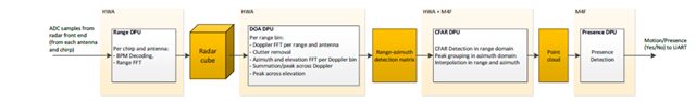
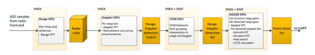
But there are still some uncertainties how the signal processing is implemented internally on the 6432. (I mainly used the Motion/Presence Detection Tuning Guide and the DPU description in the TI Resource Explorer as a basis).
Questions for offline processing:
How and in which step do I have to perform the BPM demodulation?
Should I also use the "compRangeBiasAndRxChanPhase" values for calibration in my offline signal processing?
Is it correct that I also have to use a rectangular window after the 2D FFT and set the first Doppler bin to "0"?
I am of course trying to search for this information in the source code of the demo in CSS. It would still be very helpful to have detailed documentation to refer to, like the tuning guide.

best regards

Tobias

  • Hello Tobias.

    How and in which step do I have to perform the BPM demodulation?

    You will do the demodulation on the ADC data that you collect.

    Should I also use the "compRangeBiasAndRxChanPhase" values for calibration in my offline signal processing?

    Yes.

    Is it correct that I also have to use a rectangular window after the 2D FFT and set the first Doppler bin to "0"?

    Yes that is correct.

    I am of course trying to search for this information in the source code of the demo in CSS. It would still be very helpful to have detailed documentation to refer to, like the tuning guide.

    You can refer to the demo documentation in the SDK to understand how the data is processed from raw adc to the processed radar uart output.

    Sincerely,

    Santosh

  • Hello Santosh,

    Thank you for your help. I have tried to program it, similar to how it is described here: AWR1843BOOST: Received signal separation on BPM MIMO

    Can you tell me if it is correct? Unfortunately, I have not found the relevant code section in CSS. Is BPM something that is done internally in the hardware accelerator or frontend M3 controller? If there is a MATLAB example on how you do the BPM, that would also be very helpful.

    fft_2d = np.fft.fft(rfft_1d, rfft_1d.shape[1], axis=1)
    fft_2d_norm = fft_2d / fft_2d.shape[1]
    radar_data_2dFFTMag = np.abs(fft_2d_norm) ** 2
    
    # MIMO BPM on 2D FFT data: fft_2d_norm[3,32,129,10,2], 3Rx, 32 Doppler Bins, 129 samples (rfft), 10frames, 2TX
    
    n_rx_chan = radar_data_2dFFTMag.shape[0]  #3RX
    
    # Init BPM Arrays
    bpm_even = np.zeros((n_rx_chan, fft_2d_norm.shape[1] // 2, fft_2d_norm.shape[2]), dtype=np.complex64)
    bpm_odd = np.zeros((n_rx_chan, fft_2d_norm.shape[1] // 2, fft_2d_norm.shape[2]), dtype=np.complex64)
    
    # Get the BPM MIMO data
    for i in range(n_rx_chan):
        bpm_even[i] = fft_2d_norm[i, 0::2, :, Frame_num, 0]  # Even Chirps (Sa = S1 + S2)
        bpm_odd[i] = fft_2d_norm[i, 1::2, :, Frame_num, 0]   # Odd Chirps (Sb = S1 - S2)
    
    # Reconstruct Signal
    S1 = (bpm_even + bpm_odd) / 2
    S2 = (bpm_even - bpm_odd) / 2
    print('shape S1:', S1.shape) #shape S1: (3, 16, 129)
    print('shape S2:', S2.shape) #shape S2: (3, 16, 129)
    
    #? How to multiply Values on Virtual Array?
    #compRangeBiasAndRxChanPhase 0.0 1.00000 0.00000 -1.00000 0.00000 1.00000 0.00000 -1.00000 0.00000 1.00000 0.00000 -1.00000 0.00000
    #S1_corrected = S1 * np.exp(-1j * phase_correction)
    #S2_corrected = S2 * np.exp(-1j * phase_correction)

    Another question: When I do the calibration with the Industrial Visualizer to get the compRangeBiasAndRxChanPhase values, do I need to be already in Bpm mode? Or do I have to select TDM specifically for the calibration first?Thanks again for the quick help! The answers are always very helpful for me.

    best regards Tobias

  • Hi, there:

    For BPM demodulation, there are two methods implemented in SDK L demos. 

    1) in the motion and presence detection demo, the BPM demodulation is done at range FFT as shown in the Doxygen documentation (file:///C:/ti/MMWAVE_L_SDK_05_04_00_01/docs/api_guide_xwrL64xx/MOTION_AND_PRESENCE_DETECTION_DEMO.html). 

    2) in the mmwave_demo, the BPM demodulation is done at AoA2D DPU.  As explains in the SDK L Doxygen documentation at:  file:///C:/ti/MMWAVE_L_SDK_05_04_00_01/docs/api_guide_xwrL64xx/MMWAVE_DEMO.html.  Because Doppler compensation is needed before BPM demodulation.

    Therefore, if you are working on an application that there are significant speed, then you should consider method (2).  Otherwise, you can apply BPM demod at the very beginning of the process.

    For your second questions, for phase/gain calibration measurement, if you are running motion and presence detection demo, you can program it as TDM or BPM.    But if you are running mmwave_demo, then you can only programmed as BPM mode.   Again you can search inside doxygen documentation to find these information.

    Best,

    Zigang