This thread has been locked.

If you have a related question, please click the "Ask a related question" button in the top right corner. The newly created question will be automatically linked to this question.

BOOSTXL-TUSS4470: GUI settings configuration

Part Number: BOOSTXL-TUSS4470
Other Parts Discussed in Thread: TUSS4470

Tool/software:

Hello all,

After trying out the TDC1000-C2000 EVM, we failed to get the required results on metallic tank level measurement.

We have decided to get the BOOSTXL-TUSS4770. We have started by using the provided 40khz transducer but have failed to get any good results.

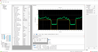
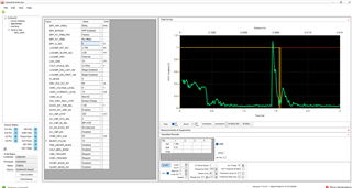
1. Below are the GUI settings we have been using. (Obstacle at 18cm)

2. Is there a significant reason why the SPI mode can't be changed in the GUI?

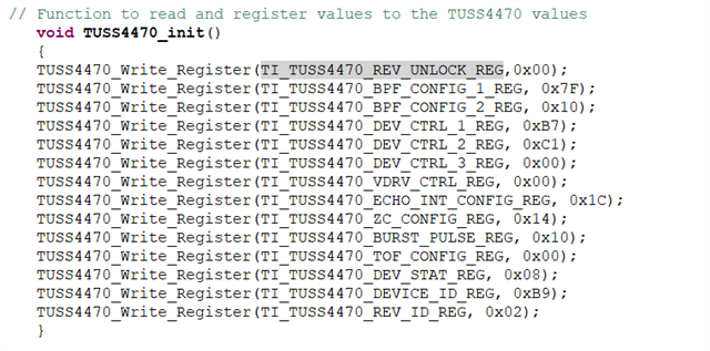
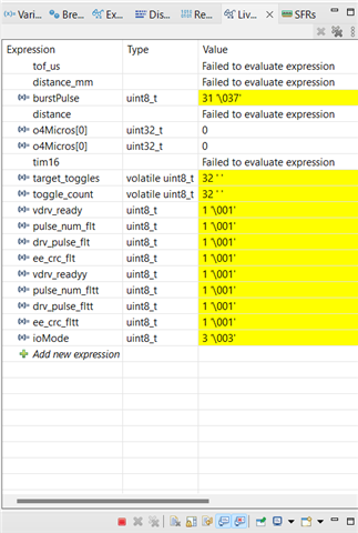
3. What are the recommended initial settings while working with this 40khz transducer.

By the way, we intend to use 1mhz transducer on a metallic LPG Cylinder at 1.2m for level measurement after these initial tests.

Regards,

Semyalo

  • Hello Seyalo,

    The video at the bottom of the FAQ page below has a good walkthrough of using the GUI that might be helpful.  

    https://e2e.ti.com/support/sensors-group/sensors/f/sensors-forum/748143/faq-ultrasonic-sensors

    Looking at your configuration, I think you could have more pulses to get a stronger echo response.  Try around 10 to 20 pulses.  

    You can start with the configuration below.  As for the fixed SPI mode, I think this was a feature that was never implemented.  

  • Hello Eddie,

    Thanks for your response. Yes, we went through the video, but the GUI used (as well as the one you have used here) does have some values that have probably been changed like the BPF_FC_TRIM. We don't have a -8 as value in the current GUI.

    Anyways, we were able to fine tune the settings and got good results for 40khz and 200khz transducers up to 2m in air. (though a <5cm distance wasn't possible).

    We are testing it out on a thin metallic container that contains water using a 1mhz transducer. After enabling HPF and inputting 1mhz as our frequency, the BPF_HPF_FREQ automatically sets to 100p. Could you elaborate more on this?

    I have attached our current settings for 1mhz transducer on a metallic container to measure water level at 75cm. It seems like we do not have any recognisable echo. Please advise on the crucial settings.

    Regards,

    Semyalo

  • See table 8-1 in the datasheet.  Be sure that you are also changing these Cinn and Cflt capacitor values for the frequency you are using.  This can have a large impact on the measurement.  J1 and J4 on the EVM can be used for this as well.      

    The device does not have a BPF that is centered at 1MHz, so you must use the HPF as it looks like you have found.  The thread below discusses how to configure.  When you enable the HPF, you can set the corner frequency.  The GUI is defaulting to 100kHz.  

    https://e2e.ti.com/support/sensors-group/sensors/f/sensors-forum/1349599/boostxl-tuss4470-boostxl-tuss4470 

    Also, if you are transmitting through the tank wall, the app note below has good information about properly mounting the transducers for best performance.

    https://www.ti.com/lit/an/snaa266a/snaa266a.pdf 

  • Hello Eddie,

    Thanks. Yes, we had already set both capacitors CFLT and CINN and now used the recommended settings from Akeem. 

    We do have some good TOF readings for 18cm in a metallic cylinder at Obj 1 in the GUI though not very stable and sometimes appears at Obj 2 or 3!

    We haven't been able to get something higher than 18cm (seems like there's a lot of noise I presume). Since we are dealing with LPG, I don't think the VDRV higher than 5V is needed for now?

    Current required level measurement is about 80cm.

    It seems like we are missing something detailed within the configuration?

    Regards,

    Semyalo

  • Hello Eddie,

    We do have our desired echo but comes with a lot of noise. 

    Do you have any advice on how we can do further filtration to get away with that?

    After enabling HBF, It seems we do get anything above the 500q/500p when using 1Mhz transducer.

    Regards,

    Semyalo

  • Semyalo,

    You could test enabling the log amp.  Section 7.3.4 of the datasheet discusses the log amp.  Give this a try and let me know if this improves your noise.    

    https://www.ti.com/lit/ds/symlink/tuss4470.pdf   

  • Hello Eddie,

    Thanks for the advice on Log amp settings. We have read through and finally reduced the noise to get acceptable readings for our 1metre LPG tank.

    We are now moving onto custom board development using STM32! I will update you on the progress. cheers!

    Regards,

    Semyalo

  • Semyalo,

    Thanks for the update.  Your echo signal looks great!

  • Eddie,

    We have since moved to program the chip using STM32 and the exact configurations that gave the accurate readings in the GUI. We saved the configuration from the GUI but we noticed it contains an additional register (DEV_TI_UNLOCK) which is not mentioned anywhere in the datasheet.

    We have tested our SPI and it works well. However, when we write to some registers such as writing a 0x00  to the TI_TUSS4470_DEV_CTRL_3_REG to configure the ioMode, when we read it back, it gives a value of 3 (Mode 3, the default) instead of Mode 0.

    Does this indicate that we cannot write to this register? How do we unlock it and all the other registers that need unlocking?

    W have been able generate the pulses on the IO2 pin and seen them with a oscilloscope.

    Here are the settings.

    We read (monitored) the status bits in the DEV_STAT register before sending a burst, and we notice that all of them are 1s.

  • Semyalo,

    Sorry about the delayed response.

    The DEV_TI_UNLOCK allows for putting the device into test mode and is a TI internal only function.  I don't recommend using this.

    Are you still having issue with writing registers?  

  • Eddie,

    We were able to write and read to the registers. We downloaded the register values that gave us good readings from the GUI and so we have been testing with those (using STM32). After a period of testing, two registers (BPF_CONFIG_1 and DEV_CRTL_2) caused the VOUT pin to have unexpected outputs.

    When we test with the setup below, the base voltage of the VOUT pin shifts from 0 to 1 (Channel 2).

    TUSS4470_Write_Register(TI_TUSS4470_BPF_CONFIG_1_REG, 0x7F);

    TUSS4470_Write_Register(TI_TUSS4470_BPF_CONFIG_2_REG, 0x10);

    TUSS4470_Write_Register(TI_TUSS4470_DEV_CTRL_1_REG, 0xB7);

    //TUSS4470_Write_Register(TI_TUSS4470_DEV_CTRL_2_REG, 0xC1);

    TUSS4470_Write_Register(TI_TUSS4470_DEV_CTRL_3_REG, 0x00);

    TUSS4470_Write_Register(TI_TUSS4470_VDRV_CTRL_REG, 0x00);

    TUSS4470_Write_Register(TI_TUSS4470_ECHO_INT_CONFIG_REG, 0x1C);

    TUSS4470_Write_Register(TI_TUSS4470_ZC_CONFIG_REG, 0x14);

    TUSS4470_Write_Register(TI_TUSS4470_BURST_PULSE_REG, 0x10);

    TUSS4470_Write_Register(TI_TUSS4470_TOF_CONFIG_REG, 0x00);


    When we disable BPF_CONFIG_1 and enable DEV_CRTL_2 the VOUT looks like this.

    //TUSS4470_Write_Register(TI_TUSS4470_BPF_CONFIG_1_REG, 0x7F);

    TUSS4470_Write_Register(TI_TUSS4470_BPF_CONFIG_2_REG, 0x10);

    TUSS4470_Write_Register(TI_TUSS4470_DEV_CTRL_1_REG, 0xB7);

    TUSS4470_Write_Register(TI_TUSS4470_DEV_CTRL_2_REG, 0xC1);

    TUSS4470_Write_Register(TI_TUSS4470_DEV_CTRL_3_REG, 0x00);

    TUSS4470_Write_Register(TI_TUSS4470_VDRV_CTRL_REG, 0x00);

    TUSS4470_Write_Register(TI_TUSS4470_ECHO_INT_CONFIG_REG, 0x1C);

    TUSS4470_Write_Register(TI_TUSS4470_ZC_CONFIG_REG, 0x14);

    TUSS4470_Write_Register(TI_TUSS4470_BURST_PULSE_REG, 0x10);

    TUSS4470_Write_Register(TI_TUSS4470_TOF_CONFIG_REG, 0x00);

    When we enable both BPF_CONFIG_1 and DEV_CRTL_2 the VOUT looks like this.

    TUSS4470_Write_Register(TI_TUSS4470_BPF_CONFIG_1_REG, 0x7F);

    TUSS4470_Write_Register(TI_TUSS4470_BPF_CONFIG_2_REG, 0x10);

    TUSS4470_Write_Register(TI_TUSS4470_DEV_CTRL_1_REG, 0xB7);

    TUSS4470_Write_Register(TI_TUSS4470_DEV_CTRL_2_REG, 0xC1);

    TUSS4470_Write_Register(TI_TUSS4470_DEV_CTRL_3_REG, 0x00);

    TUSS4470_Write_Register(TI_TUSS4470_VDRV_CTRL_REG, 0x00);

    TUSS4470_Write_Register(TI_TUSS4470_ECHO_INT_CONFIG_REG, 0x1C);

    TUSS4470_Write_Register(TI_TUSS4470_ZC_CONFIG_REG, 0x14);

    TUSS4470_Write_Register(TI_TUSS4470_BURST_PULSE_REG, 0x10);

    TUSS4470_Write_Register(TI_TUSS4470_TOF_CONFIG_REG, 0x00);

    When both registers are disabled or when their reset values are used, the VOUT output behaves as expected. Also, this strange behavior has started recently, initially we faced no such issues on the VOUT pin with the same register settings.


  • Semyalo,

    I am looking into this and expect to have an update for you by Friday(5/2) this week.

  • Eddie,

    Any update from you? 

    We still have the same issues.

    Thanks.

  • Semyalo,

    Sorry, I was out sick Fri and Mon.  I think this may be related to bits 5:4 shown below.  The datasheet mentions that Q_SEL is only valid when BPF is enabled.  If you leave this register to defaults, is the behaviour different?

  • Eddie,

    We noticed the VOUT line gets distorted when we set the HPF bit (BPF_CONFIG_1 (BIT 6). When run with BPF, the VOUT is Okay. We want to use HPF because we are using a 1 MHz transducer. The DEV_STAT_Register shows 0x08 meaning we have no device errors.

    We set the default value of BPF_CONFIG_2 as you suggested but still the same (pic below).

  • Semyalo,

    Just wanted to update you.  I am still looking into this, but not quite sure whats happening here yet.  Is your schematic based on the EVM?  Could you provide the schematic as well?  Another test you could run is to connect your MCU and code up to the EVM and see if the same issue is observed.  This could help isolate the problem.

  • Hello Eddie,

    We have been using TI TUSS4470 Boost EVM together with STM32WB09 Nucelo board using custom code. 

    We did finally solve the issue.

    The distortion was caused by EMI from the laptop adaptor, once connected to our laptop with code and enabling the 1mhz frequency in registers. When we used a different adaptor we did get great results without any noise. Once connected again the weird noise would come back in immediately have our signal distorted.

    We are currently making a final custom board. Will update you soon.

    Cheers

  • Wow, good job catching that!  Glad to hear it and thanks for the update.