This thread has been locked.

If you have a related question, please click the "Ask a related question" button in the top right corner. The newly created question will be automatically linked to this question.

IWR1843AOP: IWR1843AOP

Part Number: IWR1843AOP
Other Parts Discussed in Thread: IWRL6432AOP, , IWRL6432, MMWAVE-L-SDK, IWRL6432AOPEVM

Tool/software:

Hi friends I am new to TI radar sensors, I want to develop a low powered (Battery operated) radar sensor based product that can be used as distance sensor, People Counting Sensor, Presence Detection Sensor and later on Possibly motion and gesture detection. While going through the radar sensor portfolio I found out there are multiple sensors available and I am not sure which one to select. My requirements are as following:

1.Low Power consumption for good battery life at least for distance sensing project which needs to happen once in 2-5 minutes periodically and then idle or sleep to save power in Building Automation/Management Systems.

2. I noticed some of the radar sensors are with DSP and some are not. As per my understanding I can directly get the processed data through interface from those which are equipped with DSP and those who do not have DSP will provide the raw data and I have to use another MCU to process the data. Am I correct? 

3. If I want to go with radar sensor without DSP such as IWRL6432AOP and use my own MCU for processing the raw data, what should be the specifications of that MCU that can process the data without any issue.

4.Do Texas Instrument provide the radar signal processing driver shared/static with algorithms that can be used for my MCU to get the meaningful data?

4. If I want to go with the radar sensor with DSP such as IWR1843AOP what would be the power consumption of these sensor+DSP combined? I want to send this processed distance data to a gateway through BLE communication and for that I have to use another MCU(nrf52833) that will sit on the same PCB as sensor + DSP and receive processed data from them and send it to gateway through BLE. This is the reason I am concerned about the power consumption of the complete project. In Idle mode the nrf52833 consumes 25microAmp and while communicating it goes near 35microAmp.

Any kind of suggestion in this matter will be really helpful, Thank You.

  • Hi

    Thanks for your query. Please allow us a couple of days to respond

    Regards

  • Hello, 

    I apologize for the delayed response here, thank you for your patience. 

    1. For any power sensitive system we recommend the IWRL6432 (or IWRL6432AOP), which is currently our lowest power device. We already have example applications for this device for all of the functions that you listed (distance sensing, people tracking/counting, presence detection, gesture recognition) and most importantly this device does have idle/deep sleep modes that can be entered to save power. I would like to note however that in the future we may have devices that consume less power with similar processing capabilities. 

    2. This understanding is not necessarily correct for all of TI's radars. Most of our devices are a radar front end with an integrated MCU+HWA (some devices also have a DSP on top of this). Even for the devices without a DSP, the integrated MCU+HWA is sufficient for performing various algorithms on chip without the need for additional host processing. For example, the IWRL6432 has a programmable Arm M4F core and a HWA, the HWA (which is configurable, and controlled by code running on the M4F) does most of the heavy lifting in terms of radar processing (FFT operations, CFAR, etc...) to generate a point cloud. Then higher level algorithms which are also running on the M4F use that point cloud for additional processing (object tracking, presence detection, gesture). As you pointed out, some devices also have an integrated DSP, devices with a higher number of antennas will require more processing so some devices include the DSP to provide extra on chip processing capabilities. Additionally, we have some devices which are "front end only" devices (such as IWR6243). These devices are not programmable, the radar front end can still be configured as needed but they only output raw data to be processed by a host processor.

    3. A host MCU is not required for use with IWRL6432AOP. The 6432 device can perform the required processing on it's own. 

    4. We provide SDKs with drivers/examples/tools (Ex: MMWAVE-L-SDK).  We also include additional example projects, configurations and visualization tools in the Radar Toolbox

    5. Please refer to the power consumption numbers listed in the datasheet. 

    Best regards,

    Josh

  • Hi Josh, thanks for these information. I have few other queries related to IWR6432AOP/IWR6432 as following.

    1.What is the difference between IWR6432 and IWR6432AOP.

    2. Do we have specific interface in  IWR6432AOP/IWR6432 itself (Not the Development kit) to send the meaningful data of distance etc. to host MCU? This information is required If we want to design our own custom board.

    3.Can I control(after adding code in the provided SDK) the active mode and deep sleep mode of this radar module with GPIO interrupt from the Host MCU which will read the meaningful data from this module? This will save a lot of Power if I want to enable the operation for finding the distance in a Minute or 2 and then put it into idle or deep sleep mode instead of preprogrammed  interval such as 1Hz which will enable it 60 times per minute.

    4.Which Hardware and Software kits are needed to test the working of the IWR6432AOP/IWR6432.

    5.Can we run and test only the presence and distance demo example on the development kits? Do we have access of the application code ? What if we want a few tweaks in the application as per our requirement or need to customize something?

    6. Please explain the steps that are needed to configure the radar and read the meaningful data of presence, distance, people count etc. with these kits and what would change(in the process) when we will design our custom board and read the data again from the radar, ultimately our project requirement is to send the data to a different MCU that will send it(on BLE) further to cloud.

    7. Actually in our Project we want to place the radar sensor in the ceiling facing downward and find out the distance of the Human/object/vehicle below it. 

    Thank You.

  • Hi, 

    No problem! Please let me know if you have any additional questions.

    1.What is the difference between IWR6432 and IWR6432AOP.

    For IWRL6432AOP the antenna resides on the package itself (AOP = "Antenna on Package"), whereas the non-AOP variant would require a PCB based antenna. This means the PCB design effort (as well as cost) is reduced for the AOP variant. Performance will be similar for both devices.

    Do we have specific interface in  IWR6432AOP/IWR6432 itself (Not the Development kit) to send the meaningful data of distance etc. to host MCU?

    Yes, IWRL6432 has UART/SPI/I2C/GPIO which can be used for data output to host. Our example applications use UART for data output.

    Can I control(after adding code in the provided SDK) the active mode and deep sleep mode of this radar module with GPIO interrupt from the Host MCU which will read the meaningful data from this module?

    Yes. This is possible with MMWAVE-L-SDK and low power devices. Please refer to the LPDS Entry/Exit driver example in the SDK.
    {SDK5_INSTALL}/docs/api_guide_xwrL64xx/EXAMPLES_DRIVERS_POWER.html

    Which Hardware and Software kits are needed to test the working of the IWR6432AOP/IWR6432

    As far as evaluation modules, we have IWRL6432BOOST and IWRL6432AOPEVM. Either one of these boards + laptop and USB cable is all of the hardware you need. For software, both boards are supported by the MMWAVE-L-SDK 

    Can we run and test only the presence and distance demo example on the development kits? Do we have access of the application code ? What if we want a few tweaks in the application as per our requirement or need to customize something?

    Yes, you have full control of the application code and can make any modifications as needed per your requirements. 

    Please explain the steps that are needed to configure the radar and read the meaningful data of presence, distance, people count etc. with these kits and what would change(in the process) when we will design our custom board and read the data again from the radar, ultimately our project requirement is to send the data to a different MCU that will send it(on BLE) further to cloud.

    For evaluation with our EVM boards, you can simply connect the board to the computer with a USB cable, load the appropriate application firmware to the onboard flash memory and configure and visualize the sensor data using one of our visualization tools. 

    Regarding your plan to transmit the data over BLE and also battery powered applications, I wanted to point out this reference design we have developed using IWRL6432 that I think is a good fit, it is for a mmWave radar sensor with sub-1-GHz and Bluetooth® 5.2

    Best regards,

    Josh

  • Hi, thanks for the timely response. Below are few more queries?

    1. Is the Performance of the radar sensor same if I want to use it on ceiling facing downward  for the distance and people counting application?

    2. It is good that we can visualize the data with the provided tool which is helpful while understanding the working of the radar. But when we get the data directly from radar to the host MCU, can we also interpret it the same way(without processing) as the visualization tool does ? or there is some processing required to do on the incoming data from radar? If some processing is required how do we know what are the steps of processing(in the form of coding) and which side we have to implement, radar side or host MCU side.

    3. When we will be using the development kit we can use it for flashing the code but how do we flash the radar MCU when we will use it on our own custom board? Do we have specific instructions to follow when we design our own custom board? We will go with the IWR6432AOP version. 

    Thank You.

  • Hello, 

    Please give me a day to get back to you with answers to these follow up questions. 

    Best regards,

    Josh

  • Hello, 

    Sorry for the delay in getting back to you. I appreciate the patience. 

    1. What aspect of the performance are you referring to here? In general, the overhead/ceiling mount configuration will not have quite as long of an effective range for detecting/tracking people. This is mostly just due to the fact that less of a person is "seen" by the radar when it is overhead vs when it is wall-mounted. 

    2. The only "processing" you would need to implement on the host MCU side would be the parsing of the data that is output from the sensor, the visualizer does the same parsing and yes you could refer to the visualizer source code and interpret it in the same way. Of course the visualizer source code is in python so you may need to port it if your host MCU is running embedded C code.

    3.  Will you design your custom board with or without a dedicated QSPI flash for the 6432? If yes then your design should include a way to interface with the UART TX and RX pins of the device for flashing. In that case, the flashing procedure is the same as with the EVM, (1) set the SOP mode with the SOP pins (2) write the image to flash via UART. 

    Best regards, 

    Josh

  • Hi Josh, thanks for the response.

    1. The Performance of aspect I was asking about is related to distance that does the distance detection accuracy of an object in front of radar affects if it's mounting is overhead?

    2. If I want to use the radar sensor to find out how many people are there in the room such as washroom where should we mount it and what should be the mounting configurations?

    3. Regarding the processing on host MCU, I am concerned about the Specifications of My MCU will be sufficient to process this or not. The MCU is NRF52833 arm M4, has 512KB Flash Size and 128KB RAM but we also run a Proprietary BLE networking stack on the same MCU which takes up good amount of Flash size(That leaves lesser space for application size) and some RAM as well. So I want to know how much resource (in terms of Flash and RAM) is required ? Obviously we do not want to plot the graph just need to parse and understand the data so may be all the python code would not be required to port in Embedded C.

    4. Is this QSPI flash requires the interface with our MCU or directly EVM ? If the it does not require out MCU I do not think there is an issue with including QSPI flash, however first I will discuss it with my board design team.

    Thank You.

  • Hello, 

    1. The accuracy of the range measurement is not affected by the mounting position. 

    2. Please refer to this application brief: Best Practices for Placement and Angle of mmWave Radar Devices

    3. I can not say for certain how much space is required as we do not have any host MCU control example. You can check if Nordic provides a UART read example with their SDK for NRF52833. 

    4. IWRL6432 has the option to be run with or without it's own dedicated flash. So if you choose, a flash can be connected via qspi to IWRL6432 and IWRL6432 will boot from the application image stored there. Since you mentioned the existing flash space is very limited it seems like you will require IWRL6432 to have it's own dedicated flash for storing the radar application image. So to answer your earlier question, the flashing procedure is the same with the your custom board as with the EVM.

    Best regards,

    Josh

  • Hi Josh thanks for the clarifying the doubts.

    1.Yes Nordic provides UART read example but on top of Nordic's SDK I use Wirepas SDK and using it I have successfully used UART peripheral for reading and writing. If there is only the UART read required for data parsing there should not be an issue, however could I have an Idea that how much would be the length of data in bytes?

    2.Where could I find the python source code of visualizer which is needed to port in embedded C as you mentioned it earlier.

    Thank You.

  • Hello, 

    No problem. 

    could I have an Idea that how much would be the length of data in bytes?

    This depends on which outputs you enable to the host which itself depends on the application (for example: a simple presence detection output could be just a yes/no output for each zone which is very small; if object tracking is enabled then the output data size will vary depending on how many targets were detected in that frame; if some heatmap data output is enabled the data size will be much larger and it will depend on the chirp configuration used; etc...). This guide documents the output data packet size for all of the outputs defined in our radar demos. You can use this to determine the output size in bytes for your application.

    Where could I find the python source code of visualizer which is needed to port in embedded C as you mentioned it earlier.

    The visualizer that I was referring to is the Applications Visualizer which is part of the radar toolbox. You can download the toolbox from dev.ti.com and then the visualizer source code is found at: {RADAR_TOOLBOX_INSTALL}\tools\visualizers\Applications_Visualizer. 

    Best regards,

    Josh

  • Hello, thanks for the above information.

    I found the source code of the visualizer. Please confirm that Do I need only gui_parser.py (and dependent codes of other files that are being used in this file) file's source code to import in my MCU if want to get the meaningful data from the UART string?

    One more thing, while going through the source code I was unable to find the reference to some of the variables and functions also I could not find the data types for some variables. Can you suggest something that might be helpful to port this source code in embedded C?

    Thank You.

  • Hello, 

    The relevant visualizer source files containing the parsing code are gui_parser.py, parseFrame.py and parseTLV.py. However, please note, these files are not necessarily written in a manner in which they could be run on their own. They are only intended to be used in the context of the visualizer tool. 

    Check readAndParseUartSingleCOMPort() / readAndParseUartDoubleCOMPort() and subsequent function calls for reference parsing code. Essentially the process consists of (1) poll the uart for the magic word. (2) Read in the frame header (3) loop through the received TLVs and perform the required parsing for each TLV

    Best regards,

    Josh

  • Hi Josh, Thanks for these valuable information. I have one more query , Can we configure the baud rate of the UART (Radar Sensor) if our MCU does not have the same baud rate? What are the available baud rates for the Radar Sensor 6432 ?

    Thank You.

  • Hi, 

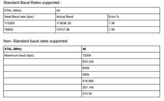
    No problem! Regarding the UART baud rate of 6432, there is some flexibility to configure the baud rate. However, due to a design limitation related to the clocking scheme the UART doesn’t support standard baud rates above 115200 bits per second. Here are the supported baud rates. See the device errata for more information.

    Best regards,

    Josh

  • Hi Josh, could we face a problem in UART communication if my MCU operates on baud rate 115200 and the radar sensor operates on baud rate 113636.36? Could it  lead to corrupt or mismatched data on receiver side?

    Additionally could we have an idea of estimated length of data bytes from the radar sensor through UART if I will only need the data of distance periodically?

    Thanks.

  • Hello, 

    could we face a problem in UART communication if my MCU operates on baud rate 115200 and the radar sensor operates on baud rate 113636.36? Could it  lead to corrupt or mismatched data on receiver side?

    This would depend on how tolerant your MCU is to baud rate mismatches. As you can see from the picture I shared, with a baud rate of 115200 the error is only 1.36%. This is generally considered an acceptable level. 

    Additionally could we have an idea of estimated length of data bytes from the radar sensor through UART if I will only need the data of distance periodically?

    The distance measurement uses the 'Detected Points Compressed' data format documented on this page. This shows the data size will be 20 Bytes + (10 Bytes x Num Detected Obj). In the level sensing demo, Num Detected Obj. is constant (configured by ZoomCfg command). 

    Best regards, 

    Josh

  • Hello, the baud rate should not be an issue now because I have configured the UART for 500000 baud rate and send the data to COM Port which was correctly detected in my Dock light app.

    I browsed to the link you shared for data format understanding, some doubts from that page are as following:

    1.This Statement "To operate this device, configurations determining the properties of the chirps transmitted from the radar are sent via configuration commands/files in a Command Line Interface (CLI) to the device via UART" was mentioned there.                                                                                        Does it mean we need to provide the configs from our MCU to the radar MCU through UART? How do we know what value would be fine for the configuring parameters and in which format or packet we need to send them to radar sensor?

    2. Can I connect the UART lines of my MCU directly on the IWRL6432AOPEVM board to receive the data in to my MCU ? 

  • Hi,

    Does it mean we need to provide the configs from our MCU to the radar MCU through UART?

    Every time the radar device is powered on it must be configured before it can begin sensing. For this we have developed a Command Line Interface (CLI) for the radar device to which individual configuration commands can be sent. We provide configuration files containing all of the required configuration commands, this makes configuring the device through PC very easy to do with a visualizer or programs like putty/tera term. This is convenient during the evaluation phase as it allows for quick iteration and testing of different configuration settings to reach the optimal performance.

    For final deployment however, many customers wish to remove the CLI interface to reduce code size/save memory and/or simplify the interface between the radar device and the host. We refer to this as hardcoded config (HCC). If that is something you are interested in it will require you to make a few code changes. It is discussed on this thread

    How do we know what value would be fine for the configuring parameters and in which format or packet we need to send them to radar sensor?

    We provide example configuration files for several applications. However, you should always perform testing for your application and you may potentially need to tune parameters to meet your requirements for performance/power/etc... The configuration commands, their parameters and format is always given in the relevant SDK documentation. For IWRL6432AOP this documentation can be found here. Additionally, we have further tuning guides to help you in selecting the right parameters. 

    Can I connect the UART lines of my MCU directly on the IWRL6432AOPEVM board to receive the data in to my MCU ? 

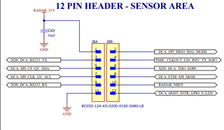
    There is a small 12 pin header on the back of the "mission board" part of the IWRL6432AOP and this includes the UART pins. THis could be used for connecting to your MCU. Please refer to the EVM schematic and user guide. 

    Best regards,

    Josh

  • Hi Josh, are you talking about the Pin Number 3 & 9, Named XDS_DCA_RS232_TX and XDS_DCA_RS232_RX ? Is it RS232 bus? if yes, we can not connect it directly to my UART bus Right? Because both have different signal levels. So I want to clarify that can I connect them to my MCU's UART bus which is 3.3V or any converter is needed?

    Thank You.

  • Hello, 

    6432's IO voltage is 3.3V. You can connect directly to the UART of your MCU. 

    Regards,

    Josh

  • Hi Josh, thanks for all these valuable information, Will create a new thread if I face any problem in the implementation.

    Thank You.