This thread has been locked.

If you have a related question, please click the "Ask a related question" button in the top right corner. The newly created question will be automatically linked to this question.

AWRL6432BOOST: Interchirp processing

Part Number: AWRL6432BOOST
Other Parts Discussed in Thread: AWRL6432

Tool/software:

Hello TI experts,

I'd like to get each chirp data.

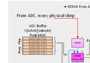
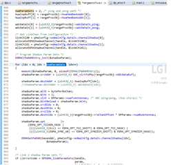
-Current Range DPU: ADC buffer ->(edma)-> HWA memory 

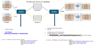
-Range DPU: ADC buffer ->(add step to get each chirp data)->HWA memory

Can I create an intermediate step to get Chirp ADC data?

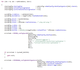
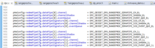
Can I get an example to reference for implementing that edma?

Thank you.

Best Regards,

JB

  • Hey Jungbum,

    Thanks for reaching out regarding obtaining raw ADC chirp data. I have looped in one of our processing experts, but please give them a day or two to look into this.

    Thank you for your patience,

    Kristien

  • Hi, JB:

    Let us assume that the ADC data is first EDMA to HWA M0.  As long as you have not overwritten that memory M0 (for example right after BPM demodulation), you can schedule an EDMA ADC data out to other memory.  This EDMA can be added similar to how range FFT output is EDMA-ed out.  

    Best,

    Zigang

  • Hi, Zigang

    I'm so sorry. I accidentally clicked the wrong button.

    Please let me know how to rollback resolved status. or Do I create new question?

    If above implementation you mentioned, I think it takes large memory size for one frame ADC data. isn't it?

    Is there any flag or trigger, callback function that notify whenever ADCbufData is updated or changed?

    Thank you.

    Best Regards,

    JB

  • Hi, JB:

    Do you plan to send ADC data out through LVDS? What do you plan to do with ADC data?   You can check the CLI command of adcLogging to see how it was implemented. 

    Best,

    Zigang

  • Hi, Zigang

    Actually, I already asked question about ADC data per chirp(https://e2e.ti.com/support/sensors-group/sensors/f/sensors-forum/1488928/awrl6432boost-how-to-get-adc-data-per-chirp)

    I started implementing EDMA structure following the interference mitigation example of AWRL1642/1843, but the EDMA function, parameters, and structure of AWRL6432 are different.

    So, I'm checking what is the flag or trigger, callback function that notify whenever ADCdataBuf is updated or changed.

    Can I ask some more questions?

    1. processing time feasibility

    In your answer from (https://e2e.ti.com/support/sensors-group/sensors/f/sensors-forum/1488928/awrl6432boost-how-to-get-adc-data-per-chirp)

    "you need to make sure that all the process (ADC buffer EDMA to ARM core memory + interference mitigation algorithm runs on ARM + EDMA the data to HWA memory + HWA do range FFT)  has to finish before the next chirps is available. "

    <ADC buffer EDMA to ARM core memory + interference mitigation algorithm runs on ARM + EDMA the data to HWA memory>

    I think this step time should be within chirp idle time, right?

    2. EDMA shadow region

    AWRL6432 use EDMA shadow region for chirp data input of range FFT.

    What is different shadow region and DPEDMA_configSyncAB ?

    Thank you.

    Best Regards,

    JB

  • Hi, JB:

    1. processing time feasibility

    In your answer from (https://e2e.ti.com/support/sensors-group/sensors/f/sensors-forum/1488928/awrl6432boost-how-to-get-adc-data-per-chirp)

    "you need to make sure that all the process (ADC buffer EDMA to ARM core memory + interference mitigation algorithm runs on ARM + EDMA the data to HWA memory + HWA do range FFT)  has to finish before the next chirps is available. "

    <ADC buffer EDMA to ARM core memory + interference mitigation algorithm runs on ARM + EDMA the data to HWA memory>

    I think this step time should be within chirp idle time, right?

    [ZY] There is a ping pong buffer, you just need to finish the above process within one chirp interval (chirpRampTime + idle time).

    2. EDMA shadow region

    AWRL6432 use EDMA shadow region for chirp data input of range FFT.

    What is different shadow region and DPEDMA_configSyncAB ?

    [ZY] The shadow EDMA region is just to auto reload the EDMA setting when the EDMA is done (bCount goes to zero) and get ready for the next round (next chirp).  

    Hope it is helpful to you.

    Best,

    Zigang

  • Hi, Zigang

    Thank you for your answer.

    I am trying to create (ADC buffer EDMA to ARM core memory + EDMA the data to HWA memory + HWA do range FFT) for one HWA loop at first. if it will be fine, I will try all HWA loop.

    I failed at second EDMA transfer. I think the trigger isn't working properly.

    Could you please check my EDMA transfer chain and function parameter set? or give me some advice?

    Thank you.

    Best Regards,

    JB

  • HI, JB:

    It will be hard for me to review your code. Are you chaining the second EDMA (from adcDataIn) to the first EDMA (from ADC data buffer to adcDataIn)? And then chaining the hotSig to the second EDMA?

    Best,

    Zigang

  • Hi, Zigang

    .

    I only changed shadowParam.destAddr to adcDataIn[idx].

    Could you please check my EDMA setting? I'm sorry for in detail code question. I'm analyzing the EDMA, but it seems like it will take more time to analyze clearly.

    .

    1. In rangeProcHWA_ConfigEDMA_DataIn()

    => Replaced from HWA memory(hwaInpBuff) to M4 adc buf memory(adcDataIn)

    Q1. Should I modify more in first EDAM(rangeProcHWA_ConfigEDMA_DataIn())?

    .

    2. Create two dataPipe channel for ping/pong transfer to HWA memory(M0,M1)

    Q2. DataIn and new two dataPipe channel has different channel number, is it right way?

    .

    3. Create rangeProcHWA_ConfigEDMA_DataPipe() function and call after rangeProcHWA_ConfigEDMA_DataIn()

    .

    4. Set two EDMA param-set of AB-sync

    * chaniningCfg 

    chainingCfg.chainingChan = pHwConfig->edmaPipeCfg.dataPipeSignature[idx].channel;
    chainingCfg.isFinalChainingEnabled = true;
    chainingCfg.isIntermediateChainingEnabled = true;

    => Set ture isFinalChainingEnabled and isIntermediateChainingEnabled for next chain trigger

    (Please let me know I set wrong value)

    .

    * DPEDMA_configSyncAB() input value

    errorCode = DPEDMA_configSyncAB(handle,
                                                                &pHwConfig->edmaPipeCfg.dataPipe[idx],
                                                                &chainingCfg,
                                                                &syncABCfg,
                                                                false, /* isEventTriggered */
                                                                false, /* isIntermediateTransferInterruptEnabled */
                                                                false, /*isFinalTransferInterruptEnabled */
                                                                NULL,
                                                                NULL,
                                                                NULL);

    .

    => isEventTriggered, isIntermediateTransferInterruptEnabled, isFinalTransferInterruptEnabled are set to false because the transfer be done immediately.(Please let me know I set wrong value)

    .

    5. Call DPEDMAHWA_configOneHotSignature()

    errorCode = DPEDMAHWA_configOneHotSignature(handle,
                                                                                        &pHwConfig->edmaPipeCfg.dataPipeSignature[idx],
                                                                                        rangeProcObj->initParms.hwaHandle,
                                                                                        rangeProcObj->dataInTrigger[idx],
                                                                                        false);

    => Call OneHotSignature function for each channel trigger.

    .

    Thank you.

    Best Regards,

    JB

  • Hi, JB:

    Ping-pong buffer EDMA is beyond my capability.  I have to look for some help.  Please give us some time to look into this. 

    Best,

    Zigang 

  • Hi, Zigang

    Thank you for help. I will wait.

    I'm wondering that the DataPipe structure for ADC buffer in mmw_demo works properly.

    because the two ADC buffer(one ADC buffer has ping and pong chirp) transfer sequentially to HWA M0 and M1 with a for-loop.

    (16xx/18xx Interference Mitigation example seems DataPipe structure transfers one ADC buffer)

    I assume that one number of ADC buffer can be used as DataPipe structure,

    but I'm not sure how about 2 number ADC buffers transfer using for-loop.


    Thank you.

    Best Regards,

    JB

  • Hi

    I would like to help you with this question.

    Have you already implemented the EDMA transfer from the ADC buffer to adcDataIn[0] and [1] Memory.

    I think this is the first part that you need to get to work 

    There are 2 EDMA channels needed, one for ping, one for pong. 

    For each transfer, when the transfer is completed there must be an ISR triggered to notify the application that the data is available.

    This must be implemented first.

    thank you

    Cesar

  • Hi Cesar,

    Thank you for coming to help.

    Before the first implementation you mentioned, I have a question.

    .

    In rangeProcHWA_ConfigEDMA_DataIn() function,

    EDMA transfer is using shadow region.

    Can I keep shadow region function? or should be changed AB-sync function? for create DataPipe between ADC buffer and HWA memory.

    .

    Thank you.

    Best Regards,

    JB

  • Hi,

    In the EDMA training the term "Shadow" is actually called "Linking" Please see training video below to understand how it works.

    Every paramset MUST have a "Shadow" paramset that will re-initialize the values after transfer is complete. The content of the Shadow paramset must be identical to the initial values.

    See Minute 18:30 in this training video

    C6000Tm embedded design workshop | TI.com

    Thank you

    Cesar