Other Parts Discussed in Thread: FDC1004
Tool/software:
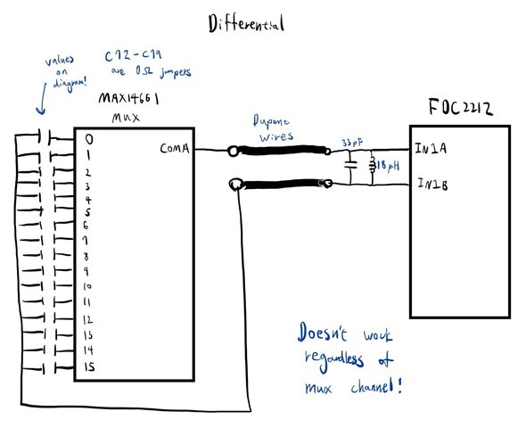
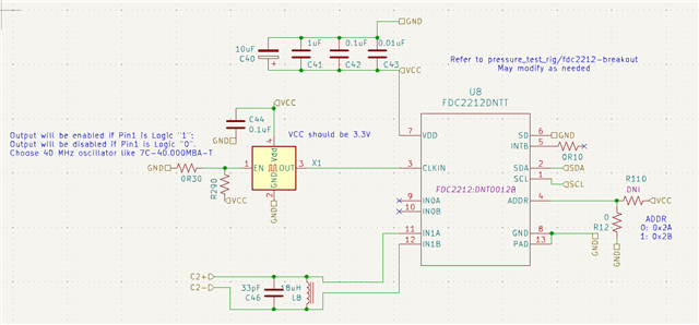
Hello everyone, I am attempting to use the FDC2212 to measure the capacitance drift of a number of SMD capacitors as they undergo various environmental temperature/pressure, and I am noticing that while it seems to work for pF range capacitors, the precision of the sensor dramatically goes down when the capacitance reaches nF levels. I am wondering if I am configuring my sensor in software incorrectly, or if I am reaching the maximum capacitance sensing range for my particular choice of inductors. Here is my circuit schematic (C+ on the MAX14661ETI_T multiplexer chip is connected to C2+ on the FDC, C- is connected to C2-, and I grounded CLKIN and am using the internal oscillator for all of these):

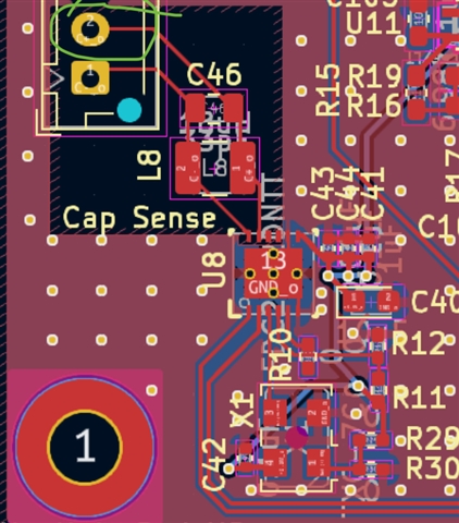
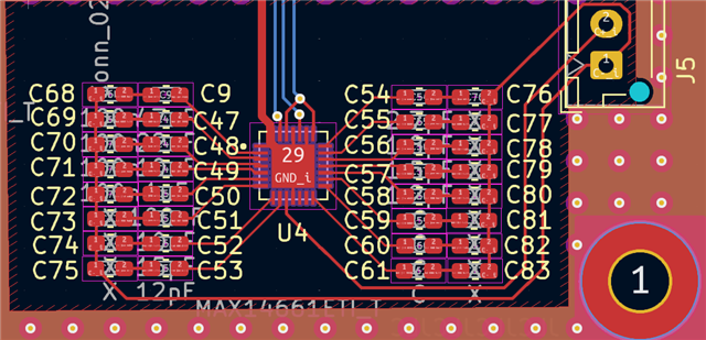
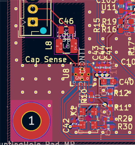
The layout are as the following, where the two boards are connected by wires (unshielded):
Now, I am aware that this is wired up in differential mode where the capacitors are getting measured across C2+ and C2-, so I did the following for the registers/capacitance measurement:
#define FDC2212_I2C_ADDR_0 (0x2A)  // Default I2C address
// Register Addresses
#define FDC2212_DEVICE_ID            0x7F
#define FDC2212_CONFIG               0x1A
#define FDC2212_MUX_CONFIG           0x1B
#define FDC2212_STATUS               0x18
#define FDC2212_DATA_CH0_MSB         0x00
#define FDC2212_DATA_CH0_LSB         0x01
#define FDC2212_DATA_CH1_MSB         0x02
#define FDC2212_DATA_CH1_LSB         0x03
#define FDC2212_RCOUNT_CH0           0x08
#define FDC2212_RCOUNT_CH1           0x09
#define FDC2212_SETTLECOUNT_CH0      0x10
#define FDC2212_SETTLECOUNT_CH1      0x11
#define FDC2212_CLOCK_DIVIDERS_CH0   0x14
#define FDC2212_CLOCK_DIVIDERS_CH1   0x15
#define FDC2212_DRIVE_CURRENT_CH0    0x1E
#define FDC2212_DRIVE_CURRENT_CH1    0x1F
// Constants for Configuration
const uint16_t CONFIG_VALUE = 0x5401;        // Conversion configuration with reserved bits set
                                             // Max current for shorter sensor activation time, chan1 continuous mode
const uint16_t MUX_CONFIG_VALUE = 0x020D;    // Channel multiplexing configuration with reserved bits set
const uint16_t RCOUNT_MAX = 0xFFFF;          // Max reference count for long integration times
const uint16_t SETTLECOUNT_VALUE = 0x0400;   // Settling reference count
const uint16_t CLOCK_DIVIDERS_VALUE = 0x1001;// Clock dividers configuration (bits 13:12)
                                             // Differential: b01: divide by 1. Chooes for sensor frequencies between 0.01MHz and 8.75MHz
                                             // Differential: b10: divide by 2. Choose for sensor frequencies between 5MHz and 10MHz
                                             // Single-ended: b10: divide by 2. Choose for sensor frequencies between 0.01MHz and 10MHz
const uint16_t DRIVE_CURRENT_VALUE = 0x8C40; // Drive current setting for each channel
// Constants for Capacitance Calculation
const double CH_FIN_SEL = 2; //use this when CLOCK_DIVIDERS_VALUE = 0x2001, use 1 when CLOCK_DIVIDERS_VALUE = 0x1001
const double fclk = 43.3e6;  // 43.3 MHz internal clock frequency (adjust if external)
const double L = 18e-6;      // 18 µH inductance
const double cap = 33e-12;   // 33 pF parasitic capacitance
// Utility functions
void writeRegister(uint8_t reg, uint16_t value) {
  Wire.beginTransmission(FDC2212_I2C_ADDR_0);
  Wire.write(reg);
  Wire.write((value >> 8) & 0xFF);  // MSB
  Wire.write(value & 0xFF);         // LSB
  Wire.endTransmission();
}
uint32_t readCapacitanceData(uint8_t msbReg, uint8_t lsbReg) {
  uint16_t msb = readRegister(msbReg);
  uint16_t lsb = readRegister(lsbReg);
  uint32_t reading = ((uint32_t)(msb & 0x0FFF) << 16) | lsb;  // Mask with 0x0FFF to ensure reserved bits are cleared
  return reading;
}
double calculateCapacitance(uint32_t reading) {
  // Calculate Fsense using a 28-bit shift and the reference frequency
  double Fsense = 2*(reading * fclk) / 268435456.0;
  // Avoid negative or overflow values in capacitance calculation
  if (Fsense <= 0) {
    Serial.println("Error: Fsense frequency is zero or negative, check the reading or circuit configuration.");
    return 0;
  }
  // Calculate Csense in pF (picofarads) with safe handling
  double Csense = (1e12) * ((1 / (L * pow(2 * PI * Fsense, 2))) - cap);
  // Serial.print("Freq: ");
  // Serial.print(Fsense*1e-6);
  // Serial.println(" MHz");
  //Serial.println(Csense);
  // Ensure Csense is non-negative
  if (Csense < 0) {
    Serial.println("Warning: Calculated capacitance is negative, likely due to overflow. Check circuit values.");
    return 0;
  }
  return Csense;
}
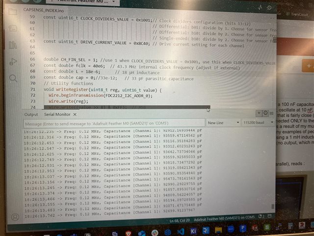
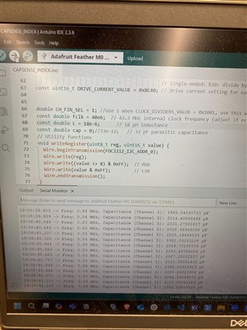
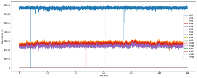
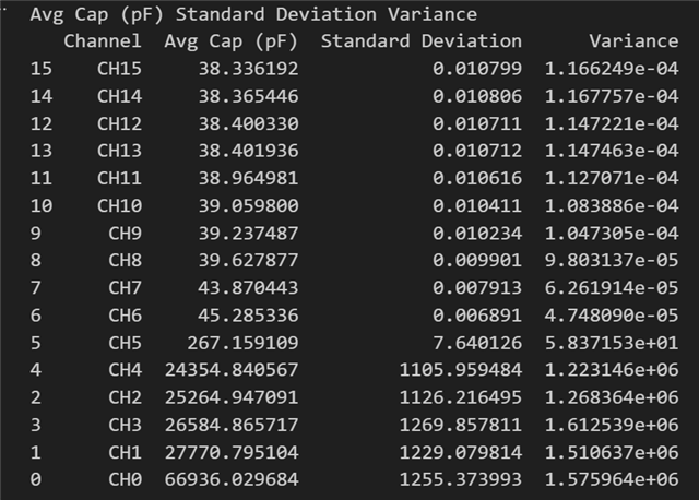
When I do that, it just outputs a negative capacitance when I measure across C68 and C9 (~100 nF). This is with the mux closed on ONLY that channel (and yes, I do see capacitances change when the mux closes on other channels instead). When I disconnected C- on the mux and grounded it instead (i.e., operated this on the single-ended mode), I switched CLOCK_DIVIDERS_VALUE to 0x2001 per the datasheet and am able to get positive (and somewhat reasonable-looking) capacitances as I switch between each channels. I logged the capacitance of all 16 channels over the course of 2 hours at 2 Hz sampling frequency and get the following statistics. Note that for CH0-5 (AB01-AB06, from 10 nF to 100 nF) the standard deviation and variance are orders of magnitude larger than the pF readings (CH12-15 are controls with no Cs installed).
Note that I saw in another forum post that FDC2212/4 does not support hot-swapping and needs to be put to sleep before you swap the output with a multiplexer, so I implemented that by setting the FDC2212 to sleep mode, waiting 50 us (I tried a longer time too like 50 ms and it doesn't make a difference), switching mux channel, waiting another 50 us, then waking it up again in my logging loop (see lines 16-21):
// Perform logging if enabled
  if (logging) {
    currentMillis = millis();
    if (currentMillis - startTime > logDuration) {
      Serial.println("Logging finished (duration elapsed).");
      file.close();
      logging = false;
      return;
    }

    file.print(currentMillis);
    Serial.print(currentMillis);

    for (int ch = 0; ch < 16; ch++) {
      // Put FDC to sleep, switch mux, wake it
      writeRegister(FDC2212_CONFIG, CONFIG_VALUE | 0x2000); // Sleep
      mux_cap.closeAllChannels();
      mux_cap.openA(ch);
      delayMicroseconds(50);
      writeRegister(FDC2212_CONFIG, CONFIG_VALUE); // Wake
      delayMicroseconds(50);

      // Wait for conversion to be ready
      uint16_t status;
      int retries = 0;
      bool valid = false;
      do {
        status = readRegister(FDC2212_STATUS);
        if (status & 0x0004) {
          valid = true;
          break;
        }
        delay(1);
        retries++;
      } while (retries < 100); // retry up to 100 ms

      if (valid) {
        uint32_t rawData = readCapacitanceData(FDC2212_DATA_CH1_MSB, FDC2212_DATA_CH1_LSB);
        double cap = calculateCapacitance(rawData);
        file.print(",");
        file.print(cap, 8);
        Serial.print(",");
        Serial.print(cap, 8);
      } else {
        file.print(",NaN");
        Serial.print(",NaN");
      }
    }

    file.println();
    Serial.println();
    file.flush();
  }
The test was done in an isolated environment with no movement/disturbance to any of the components. My understanding was that the FDC2212 was supposed to be able to measure fF level resolution capacitance up to 250 nF (or in my case with a 18 uH inductor in single-ended mode, 14 uF to 14 pF for fsense from 10 kHz to 10 MHz). My questions are:
- Why is my capacitance reading so much noisier at higher capacitances at single ended mode (nF level noise)? Is this inevitable or is there a way to lower noise at higher capacitances?
- What are some reasons why my differential reading setup doesn't work? The capacitance should be more than high enough but my code says it's less than 33 pF which gives me a negative C from the capacitance calculation equation in the datasheet.
- Is my method of switching the output with a multiplexer legitimate if I put the device to sleep like that? I'm a bit uncertain why hot-swapping wouldn't work other than increasing settling time, since I don't get how a sudden change in capacitance from switching channels is different from the sensing capacitance changing quickly.
Thank you so much for everyone's assistance!


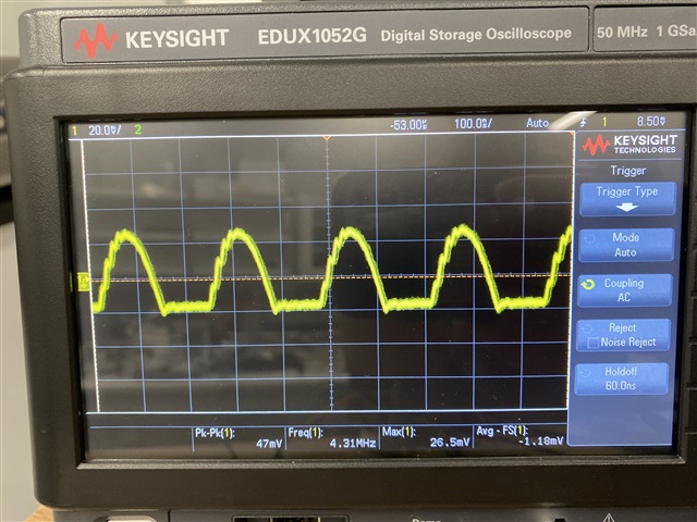
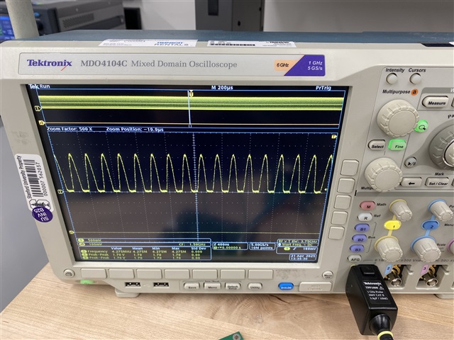
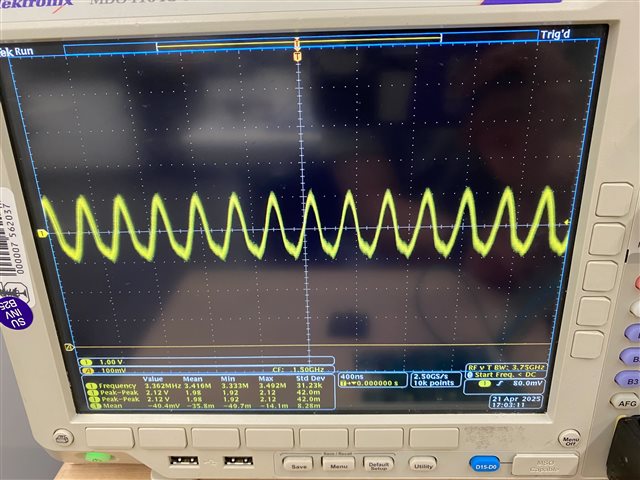
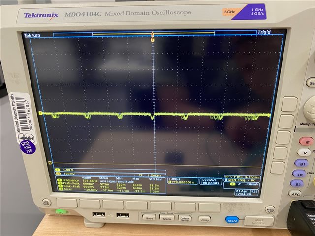
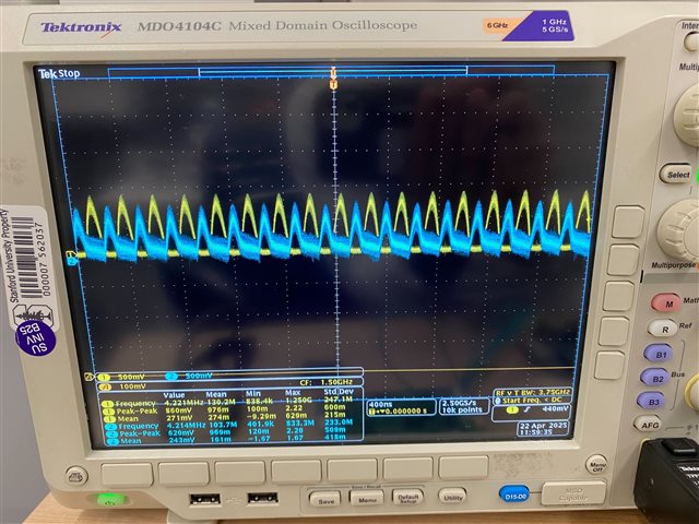
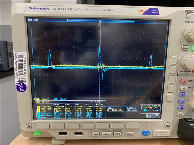
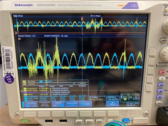
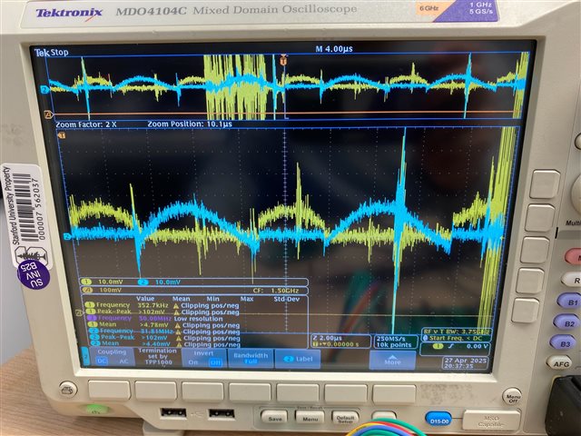
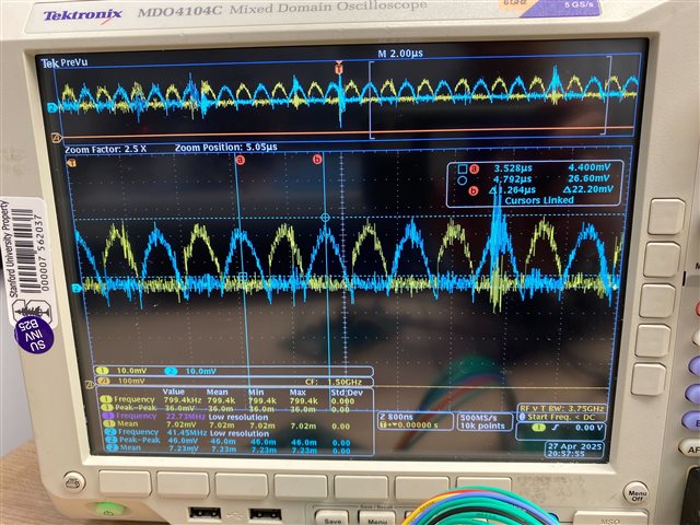
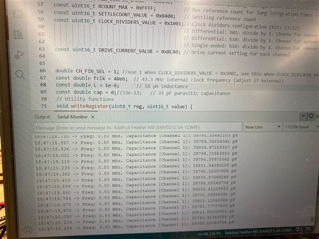
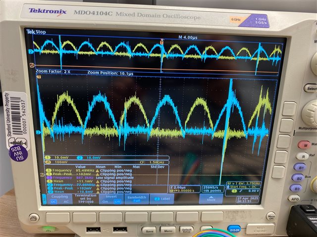
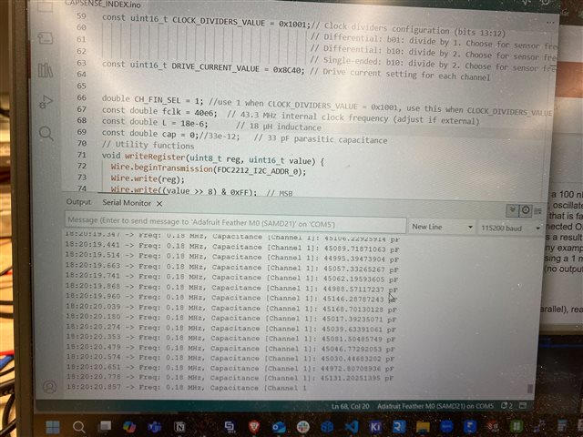
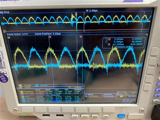
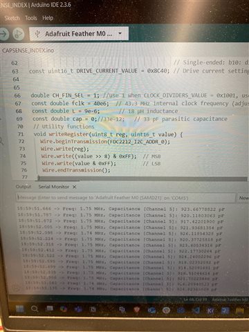
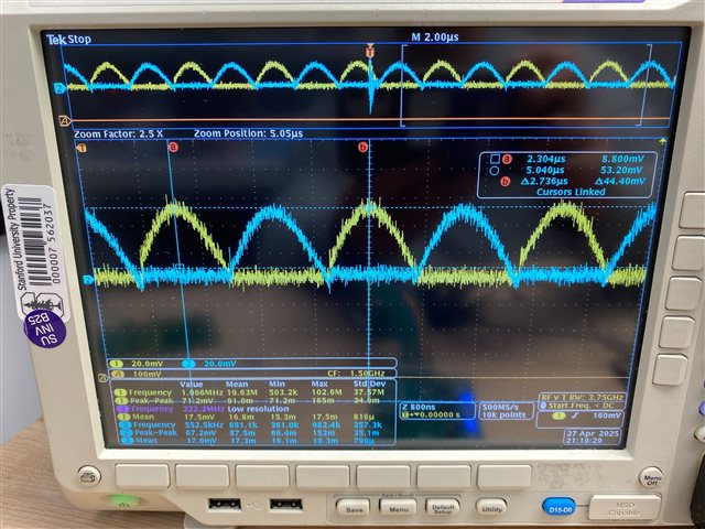
 However on my serial output I get a frequency of about 0.13 MHz according to the chip itself for channel 0, 0.32 MHz for channels 1-4, and 2.54 MHz for channel 5. For channels 6-15 I get something like this with a reported frequency if about 4.22 MHz.