Other Parts Discussed in Thread: AWR2544, DCA1000EVM
Tool/software:
Hi team,
As per recommendation, I was able to run the instrumentation LVDS based streaming on awr2544 dev kit with studio cli from radar_toolbox_2_20_00_05. However, I have an observation that the data saved into the bin file was less than expected.
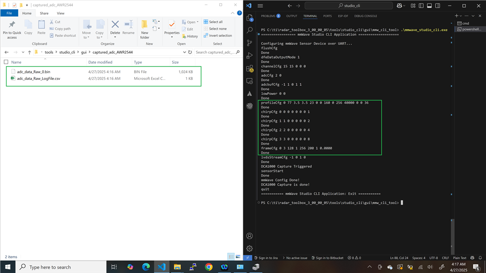
- Data collection with config #1: 1 frame, 200ms frame period, 4 Tx, 4 Rx, TDM mode, 256 ADC samples, 128 chirps. (cfg file attached).
==> Expected bin file size: (ADCSample * Chirps * nTx * nRx * bytes_per_ADCSample) = 256 * 128 * 4 * 4 * 2 = 1,048,576 Byte (or 1024KB, as awr2544 has real only ADC sample, so each sample length is 2 byte).
==> I got a bin file with 1024KB as expected.
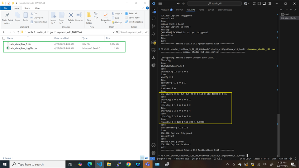
- Data collection with config #2: 1 frame, 200ms frame period, 4 Tx, 4 Rx, TDM mode, 512 ADC samples, 128 chirps. (same as cfg #1, just change number of adc sample to 512 for better range resolution)
==> Expected bin file size: (ADCSample * Chirps * nTx * nRx * bytes_per_ADCSample) = 512 * 128 * 4 * 4 * 2 = 2,097,152 Byte
==> However, I got a bin file with only 1024KB, instead of 2048KB as expected. (snapshot attached)
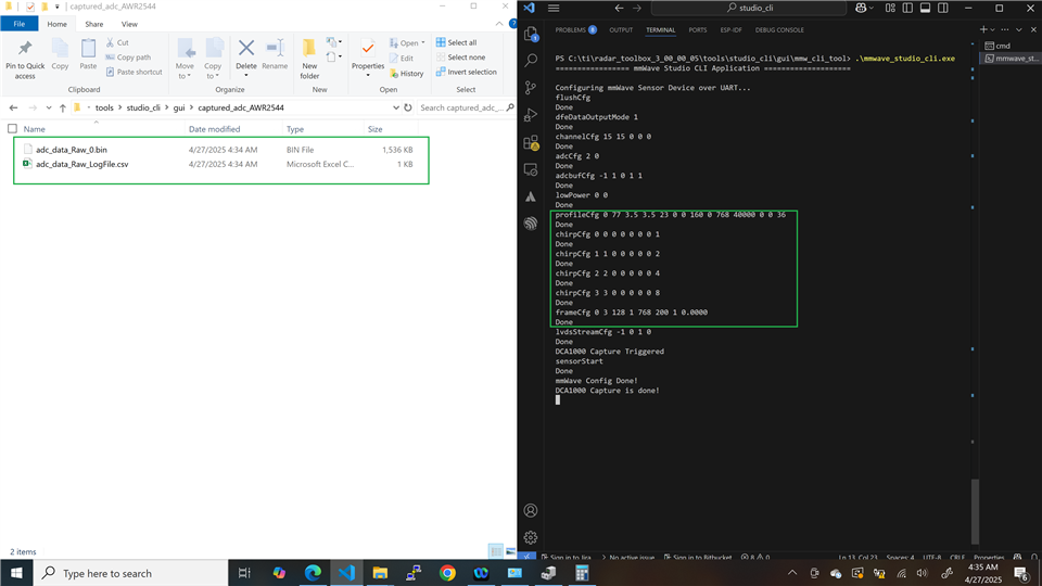
- Data collection with config #3: 1 frame, 200ms frame period, 4 Tx, 4 Rx, TDM mode, 768 ADC samples, 128 chirps. (same as cfg #1, just change number of adc sample to 768)
==> Expected bin file size: (ADCSample * Chirps * nTx * nRx * bytes_per_ADCSample) = 768 * 128 * 4 * 4 * 2 = 3,145,728 Byte
==> However, I got a bin file with only 1536KB, instead of 3072KB as expected. (snapshot attached)
I , unfortunately I couldn't figure out why the expected bin files saved only a half of expected size.
Hope TI team can help me on this observation.
Thanks,
Quoc