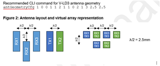
This thread has been locked.

If you have a related question, please click the "Ask a related question" button in the top right corner. The newly created question will be automatically linked to this question.

IWRL6432: Problems with calibration of custom antenna geometry

Part Number: IWRL6432

Tool/software:

We've designed our own hardware based on the IWRL6432 and everything seems to work so far. We've now tried to do a calibration based on the integrated measureRangeBiasAndChanPhase CLI command on top of your motion and presence demo firmware of the MMWAVE SDK in the version 05.05.03.00 and an anechoic chamber with a corner reflector mounted at 0.9m.

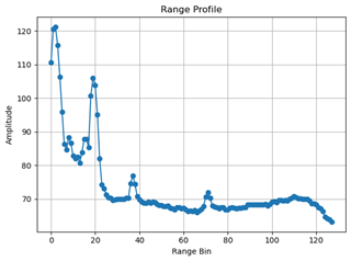
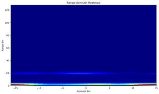
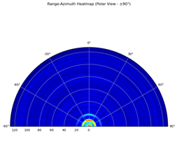
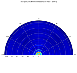
Calibration procedure works well for the IWRL6432BOOST evaluation kit. I verified it by reading out the range-azimuth heatmap with default calibration values and with the applied output of the calibration measurement.

IWRL6432BOOST uncalibrated:

IWRL6432BOOST calibrated:

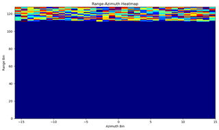
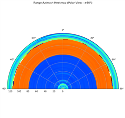
But when I do the same with our hardware I get a corrupted output after applying the calibrated values.

Uncalibrated custom hardware:

Calibrated custom hardware:


I've further also attached the .cfg files for the ISK and custom hardware which I use for the calibration and with the applied calibration values. Only difference between the BOOST and custom hardware is the starting frequency and the antenna geometry. The rest of the setup is identical.

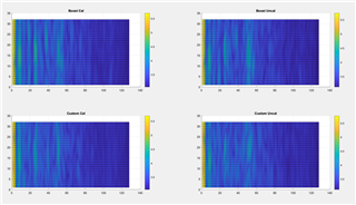
At the moment I suppose that there could be a problem with the calibration routine which struggles with our antenna geometry. It has to be said that our geometry virtual array is mirrored in elevation compared to the BOOST and that not all RX channels are length matched. Transmission line to RX2 is app. 3mm shorter compared to the ones to RX1 and RX3.

Virtual array BOOST:

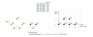
Virtual array custom hardware:

Do you have any idea what could be the reason for this problem?

Custom Hardware - Calibrated.cfgCustom Hardware - Calibration.cfgIWRL6432BOOST - Calibrated.cfgIWRL6432BOOST - Calibration.cfg

  • Hi,

    Your plot indicates that the magnitudes of targets are different in different range bins, which is not expected for this calibration, which should only affect the AOA of detected targets. Is it possible there is a data parsing error here or something similar? The heatmap you're showing seems very wrong, and I would suspect it's being decoded wrong.

    Best,

    Nate

  • Hello Nate

    Thank you for your feedback.

    I used double the bandwidth (3.072GHz) and repeated the test by also reading out the point cloud data and range profile during calibration. Here I get the following output with a calibration distance of 0.9m and a window of 0.2m:

    TLV type, headerlength, datalength: 301 8 70
    Range: 0.920, SNR: 25.25
    Range: 0.933, SNR: 31.25
    Range: 0.946, SNR: 29.5
    Range: 0.971, SNR: 21.5

    So I would expect this should work fine for the calibration algorithm as it does on the BOOST board. Further a corner reflector will always generate different magnitudes for a target so what do you mean exactly with different magnitude of targets here?

    Further I've plotted the Range-Azimuth Heatmap in cartesian format without logarithm. This works well when I run everything with the default calibration but as soon as I apply the calibration I get corrupted data here. I receive the correct TLV type and also the expected size but the parsed data is corrupted.

    Default calibration values:

    With calibration values applied:

    So I do not expect that we have a problem with the decoding here as decoding works fine for the BOOST and data already looks corrupted in the unprocessed data.

    Further I found another topic where the phase jumps between the different TX/RX antennas is described:

    https://e2e.ti.com/support/sensors-group/sensors/f/sensors-forum/1390913/awrl6432-how-to-understand-the-value-of-comprangebiasandrxchanphase

    Further I expect a phase mismatch of app. -320° for the RX2 compared to the RX1/RX3 antennas based on the missing length matching. Can you please give me a feedback if our used antGeometryCfg command is correct and your calibration algorithm can handle the phase mismatch of the different RX antennas?

  • Hi,

    I don't think the problem is with the calibration. The fact that you have such random noise values only at the top range bins suggests to me that something particularly wrong is happening underneath here. Are you running the out of box software with NO modifications? When I run the SDK 5.3.3.0 out of box demo on a BOOST EVM in my office, I see the following images. There is no strong deviation in the detection intensity between uncalibration and calibrated range-azimuth heatmaps.

    The data files from loading the range-azimuth heatmap out of the device memory can be found attached.

    /cfs-file/__key/communityserver-discussions-components-files/1023/boost_5F00_cal.dat

    /cfs-file/__key/communityserver-discussions-components-files/1023/custom_5F00_cal.dat

    /cfs-file/__key/communityserver-discussions-components-files/1023/custom_5F00_uncal.dat

    /cfs-file/__key/communityserver-discussions-components-files/1023/boost_5F00_uncal.dat

    Best,

    Nate

  • Hello Nate

    I also think that the problem is happening underneath here. I work with the out of box motion and presence demo in version 05.05.03.00 for my tests here. Both calibration configs are also working well on the BOOST on my side. I only see problems with our custom hardware and only difference here is the mirrored virtual array pattern (what I define with the antenna geometry command) and the fact that the RX channels are not length matched. So at the moment I expect that the out of box demo struggles with this phase mismatch, what generates corrupted calibration values which then generate some weird things underneath that I get corrupted data.

    Can you please give me a feedback if my antenna geometry command is correct for my shared virtual array?

    Further it would be interesting to know if the missing RX length matching is a problem or not?

  • Hi Ueli,

    Your antenna geometry command looks right to me, but I don't think the bad data you're experiencing is likely to be caused by the antenna geometry command, since the antenna geometry should not really affect the range data, and it seems like your range data is corrupted here. 

    Similarly, I would not expect your length matching to result in such a strange deviation over range. Perhaps you can post your rangeazimuth heatmap data here so we can take a look. I will also add our HW team to consult.

    Best,

    Nate

  • Hello Nate

    Thank you for your feedback here. That's the same what we would have expected. I'm now in direct contact with Greg and he took you CC. I've sent him a feedback where I've added the rangeazimuth heatmap data in an excel.

  • Excellent. We will correspond offline then.

    Best,

    nate