AWRL6844: QSPI communication

Part Number: AWRL6844
Other Parts Discussed in Thread: , UNIFLASH, SYSCONFIG

Tool/software:

Hi, 

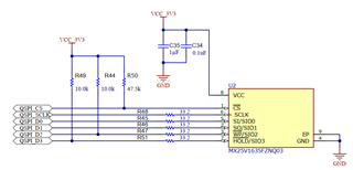
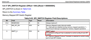
I'm working on a simple application that uses QSPI communication. I'm not using the memory-mapped protocol translator; instead, I'm configuring the core SPI module directly.

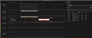
I'm encountering an issue when reading data from the QSPI flash. Transmitting works fine, and I can see on the logic analyzer that the flash device responds with data. However, the SPI_DATA register contains 0x00000000 at the end of each transaction.

I've tried using both Mode 0 (CKP=0, CKPH=0) and Mode 3 (CKP=1, CKPH=1), but the issue persists in both cases.

Has anyone encountered a similar problem or have suggestions on what might be wrong?

Best regards

  • Hey Jaka,

    Thanks for reaching out regarding interfacing with your flash device. I have looped in one of our flash experts, but I had two questions to help us understand your setup:

    1. Just to confirm, you are using the AWRL6844's SPI module to communicate with a QSPI flash device, correct? Is there a particular reason why you cannot utilize the AWRL6844's QSPI module instead?
    2. Could you give the part number of the flash device you are using?

    Regards,

    Kristien

  • Hi Kristien,

    I’m using the QSPI module to communicate with the flash memory. Since I also need to send commands like JEDEC ID reads and other flash register reads (not just standard read/write operations), I’m using Config Port mode instead of the memory-mapped protocol translator.

    I'm working with the AWRL6844EVM board and the MX25V1635FZNQ03 flash. However, I don’t believe the issue is related to the flash itself, as it seems to respond with the correct data.

    The problem is that I can’t observe the response data in the SPI_DATAx registers.


  • Hi Jaka, 

    Please give me a few days to look further into this issue and get back to you.

    Best,

    Vignesh K.

  • Hi Vignesh,

    is there anything new about the issue?

    Best regards, 
    Jaka

  • Hi Jaka, 

    I apologize for the delay. Here are some points

    1. Are you able to read back the JEDEC ID of the flash? If you can, then try the next number point
    2. Can you try sending an erase command before writing then try reading back

    Additionally, we have an example in the SDK which has a QSPI flash transfer example. I understand that you do not want to use the memory-mapped protocol translator because you still want to be able to send commands. You can use it in memory mapped protocol and still send commands. You can find the example here: [MMWAVE_L_SDK_06_00_05]\mmwave_l_sdk_06_00_05_01\examples\drivers\qspi\qspi_flash_transfer\qspi_flash_transfer.c

    Best,

    Vignesh K.

  • Hi Vignesh,

    Regarding the point first point, I'm unable to read the JEDEC ID. With a logic analyzer attached to the QSPI lines, I can see that the flash responds with the correct ID. However, the value does not appear in the DATA registers of QSPI module.

    Best regards,
    Jaka

  • Hi Jaka,

    Since you are seeing that the JEDEC ID is being sent and just not being recognized by the device, I suspect that your QSPI might still be busy during this time. 

    Could you check your QSP_STATUS_REG(0) and seeing whether it is still busy or not.

    Best,

    Vignesh K.

  • Hi Vignesh,

    After sending JEDEC ID command and trying to read 3 bytes response, the SPI_STATUS has value 0x00040006, meaning that word complete bit set, Frame complete bit set and word count 4. The BUSY bit is 0 which means that the transfer is not in progress. I really don't know what else could be the reason for that behaviour.


    Best regards,
    Jaka

  • I'm not sure if this is related to the issue I'm describing, but I can't set the WLEN field of the SPI_CMD register to a value higher than 0x1F.
    According to the TRM, 0x7F (127) should be used to select a 128-bit word length (meaning all four 32-bit data registers), but this configuration doesn't seem to work.

    Is there any known issue with the QSPI controller?

    I've also tried connecting and loading the QSPI example from the SDK using Code Composer Studio, but I’m unable to connect to the controller. The following error is reported:
    Error connecting to the target: (Error -2062 @ 0x0)

    Interestingly, Uniflash does manage to connect to the core, so I believe the jumpers and DIP switches are correctly configured.

    At this point, I'm not sure what else to try. Any useful suggestions would be appreciated.

  • What is the status here? Can anyone help me please.

  • Hi Jaka, 

    I apologize for the late response here. There is no known issue with the QSPI controller and we have not experienced anything like this. Can you share your code or project with us? Are you modifying a demo or pre-existing project to try to use the QSPI module in this manner?

    Regarding your issue with connecting to the target, does this happen when you try connecting to the core for debug? If so, please try the steps under FAQ#1 under the EVM section or FAQ#3 under the SDK 6.0.3.0 section of the FAQ: AWRL6844.

    Best,

    Vignesh K.

  • Hi Vignesh,

    Unfortunately, I cannot share the entire project, but I can provide the main files that contain all the functions for transmitting/receiving the SPI scan. Similar libraries work correctly for other AWRx devices (with their respective header files defining addresses and registers for each controller).

    As mentioned, the functions work fine for transmitting SPI sequences. The only issue is that the response from the SPI chip (visible on the SPI lines) is not appearing in the DATA registers.

    Regarding the CSS Studio and the connection to the SoC, unfortunately, I am still unable to connect with same error code, even after following the steps you provided in your last response.

    Best regards,

    Jaka

    #include "MonitorFeatures.h"
    #include "..\UMI3\UMI3_Engine.h"
    #include "..\UMI3\Monitor_Utils.h"
    
    #include "DeviceOperations_AWRL6844QSPI.h"
    #include "cslr_soc_baseaddress.h"
    #include <string.h>
    #include <qspi.h>
    #include <ClockP.h>
    
    #define RTIDWDCTRL  (*((volatile DWORD *) 0x50020090))
    #define RTIWDSTATUS (*((volatile DWORD *) 0x50020098))
    #define RTIDWDKEY   (*((volatile WORD *) 0x5002009C))
    
    /////////////////////////////////////////////////////////////////////////////////////
    ////Device_Specific_Defines_And_Functions////////////////////////////////////////////
    /////////////////////////////////////////////////////////////////////////////////////
    
    uint32_t g_qspiHandle = NULL;
    QSPI_Params g_qspi_params;
    QSPI_Object *object;
    
    QSPI_Config gQspiConfig[];
    QSPI_Attrs *gQSPIAttr;
    
    EDMA_Config gEdmaConfig[];
    uint32_t gQspiConfigNum = 1;
    uint32_t gEdmaConfigNum = 1;
    
    ClockP_Config gClockConfig;
    
    
    CSL_app_cfg_qspiRegs *g_pQspiRegs = (CSL_app_cfg_qspiRegs *)CSL_APP_CFG_QSPI_U_BASE;
    
    static void s_Qspi_waitIdle()
    {
      /* Wait while QSPI is busy */
      uint32_t dwQspiStatusReg = CSL_REG32_RD(&g_pQspiRegs->SPI_STATUS);
      while ((dwQspiStatusReg & CSL_APP_CFG_QSPI_SPI_STATUS_BUSY_MASK) == CSL_QSPI_SPI_STATUS_REG_BUSY_BUSY)
        dwQspiStatusReg = CSL_REG32_RD(&g_pQspiRegs->SPI_STATUS);
    }
    
    static uint8_t s_getCmdRegCmdPins(bool bWrite, uint8_t byNumPins)
    {
      /* Write supports 4-pin operations (data out on D0 - MOSI, data in on D1 - MISO) or 3-pin operations (data out/in
         on D0 - some sort of multiplexed SPI, so avoid for now) */
      if (bWrite)
        return CSL_QSPI_SPI_CMD_REG_CMD_FOUR_PIN_WRITE_SINGLE;
    
      /* Read supports 3, 4 or 6-pin operations (data read on 1, 2 or 4 input pins) */
      switch (byNumPins)
      {
      case 1: return CSL_QSPI_SPI_CMD_REG_CMD_FOUR_PIN_READ_SINGLE;
      case 2: return CSL_QSPI_SPI_CMD_REG_CMD_FOUR_PIN_READ_DUAL;
      case 4: return CSL_QSPI_SPI_CMD_REG_CMD_SIX_PIN_READ_QUAD;
      default: return CSL_QSPI_SPI_CMD_REG_CMD_FOUR_PIN_WRITE_SINGLE;
      }
    }


    void initClocks()
    { 
    
      APP_RCM_LOCK0_KICK0 = RCM_KICK0;
      APP_RCM_LOCK0_KICK1 = RCM_KICK1;
      
      APP_QSPI_CLKCTL_REG = 0x03334440; // DIVR 1, SRCSEL - fast clk, GATE 0 (enable clock)
      APP_RCM_LOCK0_KICK0 = RCM_KICK_LOCK;
      APP_RCM_LOCK0_KICK1 = RCM_KICK_LOCK;
    
    }
    
    void initGPIO()
    {
      // Unclock pad config registers
      IOCFGKICK0_REG = IOCFGKICK0_KEY;
      IOCFGKICK1_REG = IOCFGKICK1_KEY;
    
      // Set pads to appropriate modes and allow hardware control
      PAD_CFG_QSPI_0_REG  &= ~(QSPI_MODE_MASK | IE_OVERRIDE_CTRL | OE_OVERRIDE_CTRL);
      PAD_CFG_QSPI_1_REG  &= ~(QSPI_MODE_MASK | IE_OVERRIDE_CTRL | OE_OVERRIDE_CTRL);
      PAD_CFG_QSPI_2_REG  &= ~(QSPI_MODE_MASK | IE_OVERRIDE_CTRL | OE_OVERRIDE_CTRL);
      PAD_CFG_QSPI_3_REG  &= ~(QSPI_MODE_MASK | IE_OVERRIDE_CTRL | OE_OVERRIDE_CTRL);
      PAD_CFG_QSPI_CLK_REG &= ~(QSPI_MODE_MASK | IE_OVERRIDE_CTRL | OE_OVERRIDE_CTRL);
      PAD_CFG_QQSPI_CS_REG &= ~(QSPI_MODE_MASK | IE_OVERRIDE_CTRL | OE_OVERRIDE_CTRL);
    }
    
    
    BOOL Device_Init(DWORD dwFlags)
    {
      gQspiConfigNum = 1;
      uint32_t errcode;
      // Set CPU clock to 200 Mhz
      initClocks();
      // Configure QSPI pads
      initGPIO();
      
      /* Set the SPI idle mode and wait for it to be idle */
      g_pQspiRegs->SYSCONFIG = CSL_APP_CFG_QSPI_SYSCONFIG_IDLEMODE_NO_IDLE << CSL_APP_CFG_QSPI_SYSCONFIG_IDLEMODE_SHIFT;
      s_Qspi_waitIdle();
    
      g_pQspiRegs->SPI_DC = CSL_APP_CFG_QSPI_SPI_DC_CKP0_RESETVAL  ; /* Clock polarity: low when data not being transfered,
                                                                     Chip select polarity: active low
                                                                     Clock phase: data shifted out on falling clock polarity,
                                                                              in on rising edge
                                                                     Data delay: same cycle as CS goes active */
    
      /* Clear the interrupts and interrupt status */
      g_pQspiRegs->INTR_ENABLE_CLEAR |= CSL_APP_CFG_QSPI_INTR_ENABLE_SET_FIRQ_ENA_SET_MASK |
                                            CSL_APP_CFG_QSPI_INTR_ENABLE_SET_WIRQ_ENA_SET_MASK;
      g_pQspiRegs->INTR_STATUS_ENABLED_CLEAR |= CSL_APP_CFG_QSPI_INTR_STATUS_ENABLED_CLEAR_FIRQ_ENA_MASK |
                                                CSL_APP_CFG_QSPI_INTR_STATUS_ENABLED_CLEAR_WIRQ_ENA_MASK;
    
      g_pQspiRegs->SPI_SWITCH = CSL_APP_CFG_QSPI_SPI_SWITCH_RESETVAL; /* Disable memory mapped mode */
    
      /* Set QSPI data clock's divider and enable it */
      g_pQspiRegs->SPI_CLOCK_CNTRL = CSL_APP_CFG_QSPI_SPI_CLOCK_CNTRL_CLKEN_RESETVAL;
      g_pQspiRegs->SPI_CLOCK_CNTRL |= 0 << 0;
      g_pQspiRegs->SPI_CLOCK_CNTRL |= CSL_QSPI_SPI_CLOCK_CNTRL_REG_CLKEN_DCLOCK_ON
                                          << CSL_APP_CFG_QSPI_SPI_CLOCK_CNTRL_CLKEN_SHIFT;
    
      return TRUE;
    }
    
    void Device_Idle()
    {
    
    }
    
    BOOL Device_Deinit(DWORD dwFlags)
    {
      return TRUE;
    }
    
    /* 
     * Device_Scan function called from UMI monitor. 
     * dwNumBytes         : num of bytes to read + num of address bytes
     * dwFlags            : num of data pins to use when sending/receiving commands, address, data
     *                      check GetNumInstrPinsFromFlags(), GetNumAddrPinsFromFlags(), GetNumDataPinsFromFlags()
     * byNumAddressBytes  : num of address bytes    
     * byNumDummyClocks   : num of dummy clocks
     * dwBytesToRead      : num of bytes to read
     * byCMD              : command to send
     * pbyDataStream      : pointer, data to send
     * g_abyReadBuff      : pointer, read buffer
    */
    BOOL Device_Scan(DWORD dwNumBytes, DWORD dwFlags, BYTE byNumAddressBytes, 
                     BYTE byNumDummyClocks, DWORD dwBytesToRead, BYTE byCMD,
                     BYTE * pbyDataStream, BYTE * pbyReadBuff)
    {
      uint8_t byNumInstrPins = GetNumInstrPinsFromFlags(dwFlags);
      uint8_t byNumAddrPins  = GetNumAddrPinsFromFlags(dwFlags);
      uint8_t byNumDataPins  = GetNumDataPinsFromFlags(dwFlags);
    
      const uint8_t c_byWriteTransferBytePackSize = 16;
      const uint8_t c_byReadTransferBytePackSize  = 16;
      uint32_t      dwBytesToWrite                = dwNumBytes - byNumAddressBytes;
    
      /* Frame length determines for how many read/write words QSPI module will keep CS pulled low once the transmission
         starts. */
      uint32_t frameLength = 1 +                                              /* Command byte - always one byte */
                             (byNumAddressBytes + 3) / 4 +                    /* Can transfer 4 byte address at once */
                             (byNumDummyClocks + 127) / 128 +                 /* Up to 128 dummy clocks (bits) at once*/
                             dwBytesToRead / c_byReadTransferBytePackSize +   /* 16 byte packed reads */
                             dwBytesToRead % c_byReadTransferBytePackSize +   /* Per byte reads */
                             dwBytesToWrite / c_byWriteTransferBytePackSize + /* 16 byte packed writes */
                             dwBytesToWrite % c_byWriteTransferBytePackSize;  /* Per byte writes */
    
        
      g_pQspiRegs->SPI_SWITCH = ~(1 << 0); // Clear MMPT_S
    
      /* Send command to the flash - always as first instruction */
      uint32_t dwQSPIx_SPI_CMD = QSPI_CS0 << CSL_APP_CFG_QSPI_SPI_CMD_CSNUM_SHIFT |
                                     (8 - 1) << CSL_APP_CFG_QSPI_SPI_CMD_WLEN_SHIFT |
                                     s_getCmdRegCmdPins(true, byNumInstrPins) << CSL_APP_CFG_QSPI_SPI_CMD_CMD_SHIFT |
                                     (frameLength - 1) << CSL_APP_CFG_QSPI_SPI_CMD_FLEN_SHIFT;
    
      s_Qspi_waitIdle();
      //g_pQspiRegs->SPI_DC |= ((CSL_APP_CFG_QSPI_SPI_DC_CKP0_MAX << CSL_APP_CFG_QSPI_SPI_DC_CKP0_SHIFT) | (CSL_APP_CFG_QSPI_SPI_DC_CKPH0_MAX << CSL_APP_CFG_QSPI_SPI_DC_CKPH0_SHIFT)); 
      g_pQspiRegs->SPI_DATA = byCMD; __asm__("DMB"); /* Write command to data register */
      g_pQspiRegs->SPI_CMD  = dwQSPIx_SPI_CMD;   /* Process Tx command - command out */
    
      /* Send address bytes if any */
      if (byNumAddressBytes)
      {
        uint32_t dwAddress = GetAddressFromBuffer(pbyDataStream, byNumAddressBytes);
        pbyDataStream += byNumAddressBytes;
    
        dwQSPIx_SPI_CMD = QSPI_CS0 << CSL_APP_CFG_QSPI_SPI_CMD_CSNUM_SHIFT |
                              ((byNumAddressBytes * 8) - 1) << CSL_APP_CFG_QSPI_SPI_CMD_WLEN_SHIFT |
                              s_getCmdRegCmdPins(true, byNumAddrPins) << CSL_APP_CFG_QSPI_SPI_CMD_CMD_SHIFT |
                              (frameLength - 1) << CSL_APP_CFG_QSPI_SPI_CMD_FLEN_SHIFT;
    
        s_Qspi_waitIdle();
        g_pQspiRegs->SPI_DATA = dwAddress; __asm__("DMB"); /* Write address to data register */
        g_pQspiRegs->SPI_CMD  = dwQSPIx_SPI_CMD;       /* Process Tx command - address out */
      }
    
      /* Send dummy bytes if any */
      if (byNumDummyClocks > 0)
      {
        dwQSPIx_SPI_CMD = QSPI_CS0 << CSL_APP_CFG_QSPI_SPI_CMD_CSNUM_SHIFT |
                              s_getCmdRegCmdPins(true, byNumDataPins) << CSL_APP_CFG_QSPI_SPI_CMD_CMD_SHIFT |
                              (frameLength - 1) << CSL_APP_CFG_QSPI_SPI_CMD_FLEN_SHIFT;
    
        /* Keep data pins low when transferring dummy bytes */
        s_Qspi_waitIdle();
        g_pQspiRegs->SPI_DATA  = 0;
        g_pQspiRegs->SPI_DATA1 = 0;
        g_pQspiRegs->SPI_DATA2 = 0;
        g_pQspiRegs->SPI_DATA3 = 0;
        __asm__("DMB");
    
        /* Max 128 dummy clocks (bits) can be transferred at once */
        do
        {
          uint8_t byNumDummyClocksNow = byNumDummyClocks > 128 ? 128 : byNumDummyClocks;
          dwQSPIx_SPI_CMD &= ~CSL_APP_CFG_QSPI_SPI_CMD_WLEN_MASK;
          dwQSPIx_SPI_CMD |= byNumDummyClocksNow;
    
          s_Qspi_waitIdle();
          g_pQspiRegs->SPI_CMD = dwQSPIx_SPI_CMD; /* Process Tx command - dummy clocks */
    
          byNumDummyClocks -= byNumDummyClocksNow;
        } while (byNumDummyClocks);
      }
    
      if (dwBytesToRead)
      {
        /* Read data */
        /* Use 16 byte (128 bit) transmissions for faster speed */
        dwQSPIx_SPI_CMD = QSPI_CS0 << CSL_APP_CFG_QSPI_SPI_CMD_CSNUM_SHIFT |
                              ((c_byReadTransferBytePackSize * 8) - 1) << CSL_APP_CFG_QSPI_SPI_CMD_WLEN_SHIFT |
                              s_getCmdRegCmdPins(false, byNumDataPins) << CSL_APP_CFG_QSPI_SPI_CMD_CMD_SHIFT |
                              (frameLength - 1) << CSL_APP_CFG_QSPI_SPI_CMD_FLEN_SHIFT;
    
        uint32_t *pdwReadBuff = (uint32_t *)(((uint32_t)pbyReadBuff + 3) & 0xFFFFFFFC);
        s_Qspi_waitIdle();
        for (uint32_t i = dwBytesToRead / c_byReadTransferBytePackSize; i > 0; i--)
        {
          g_pQspiRegs->SPI_CMD = dwQSPIx_SPI_CMD;
          s_Qspi_waitIdle();
    
          *pdwReadBuff++ = swap_DWORD(g_pQspiRegs->SPI_DATA3);
          *pdwReadBuff++ = swap_DWORD(g_pQspiRegs->SPI_DATA2);
          *pdwReadBuff++ = swap_DWORD(g_pQspiRegs->SPI_DATA1);
          *pdwReadBuff++ = swap_DWORD(g_pQspiRegs->SPI_DATA);
          __asm__("DMB");
        }
        dwBytesToRead %= c_byReadTransferBytePackSize;
    
        /* Transfer the rest of the bytes (non 16 byte packed) one by one */
        dwQSPIx_SPI_CMD &= ~CSL_APP_CFG_QSPI_SPI_CMD_WLEN_MASK;
        dwQSPIx_SPI_CMD |= (8 - 1) << CSL_APP_CFG_QSPI_SPI_CMD_WLEN_SHIFT;
        while (dwBytesToRead)
        {
          g_pQspiRegs->SPI_CMD = dwQSPIx_SPI_CMD; /* Process Rx command - data in*/
    
          /* Wait for QSPI to finish the transaction and copy received data from its register(s) */
          s_Qspi_waitIdle();
          *pbyReadBuff++ = (uint8_t)g_pQspiRegs->SPI_DATA;
          __asm__("DMB");
    
          dwBytesToRead--;
        }
      }
      else if (dwBytesToWrite)
      {
        /* Write data */
        /* Use 16 byte (128 bit) transmissions for faster speed */
        dwQSPIx_SPI_CMD = QSPI_CS0 << CSL_APP_CFG_QSPI_SPI_CMD_CSNUM_SHIFT |
                              ((c_byWriteTransferBytePackSize * 8) - 1) << CSL_APP_CFG_QSPI_SPI_CMD_WLEN_SHIFT |
                              s_getCmdRegCmdPins(true, byNumDataPins) << CSL_APP_CFG_QSPI_SPI_CMD_CMD_SHIFT |
                              (frameLength - 1) << CSL_APP_CFG_QSPI_SPI_CMD_FLEN_SHIFT;
        for (uint32_t i = dwBytesToWrite / c_byWriteTransferBytePackSize; i > 0; i--)
        {
          s_Qspi_waitIdle();
    
          /* Fill the data buffers */
          g_pQspiRegs->SPI_DATA = swap_DWORD(ToDWORD(pbyDataStream)); pbyDataStream += 4;
          g_pQspiRegs->SPI_DATA1 = swap_DWORD(ToDWORD(pbyDataStream)); pbyDataStream += 4;
          g_pQspiRegs->SPI_DATA2 = swap_DWORD(ToDWORD(pbyDataStream)); pbyDataStream += 4;
          g_pQspiRegs->SPI_DATA3  = swap_DWORD(ToDWORD(pbyDataStream)); pbyDataStream += 4;
          __asm__("DMB"); 
    
          g_pQspiRegs->SPI_CMD = dwQSPIx_SPI_CMD;
        }
        dwBytesToWrite %= c_byWriteTransferBytePackSize;
    
        /* Transfer the rest of the bytes (non 16 byte packed) one by one */
        dwQSPIx_SPI_CMD &= ~CSL_APP_CFG_QSPI_SPI_CMD_WLEN_MASK;
        dwQSPIx_SPI_CMD |= (8 - 1) << CSL_APP_CFG_QSPI_SPI_CMD_WLEN_SHIFT;
    
        while (dwBytesToWrite)
        {
          s_Qspi_waitIdle();
    
          g_pQspiRegs->SPI_DATA = *pbyDataStream; __asm__("DMB"); /* Fill transmit buffer with data byte */
          g_pQspiRegs->SPI_CMD  = dwQSPIx_SPI_CMD;            /* Start transmission */
    
          dwBytesToWrite--;
        }
      }
    
      return TRUE;
    }
    
    
    DeviceOperations_AWRL6844QSPI.h

  • Hi Jaka,

    Thank you for sending me your code, give me a few days to look into and see what I can find.

    Best,

    Vignesh K.

  • Hi Jaka,

    I have looked through your code and it is difficult to say where the issue lies because there are many potential issues. I suggest to use the SYSCONFIG tool in CCS, create a new instance for the QSPI driver and build the project. This will create a set of files which will have all of your correct QSPI settings ready so that all you have to do is call Drivers_open(); Board_driversOpen(); then you can use all the functions in the QSPI drivers seamlessly..

    By doing everything manually you introduce a large room for error and the SYSCONFIG tool was implemented to reduce the overhead required to setup drivers. In your implementation it looks like you aren't using our drivers properly for QSPI. 

    Let me know if you want more guidance on how to use SYSCONFIG.

    Best,

    Vignesh K.

  • Hi Vignesh,

    I tried a few examples from the CSS, and the symptoms are similar to what I described before. I tested

    • qspi_flash_dma_transfer_xwrL684x-evm_r5fss0-0_nortos_ti-arm-clang 
    • qspi_flash_transfer_xwrL684x-evm_r5fss0-0_nortos_ti-arm-clang 

    with both the default configuration and with the library manually configured via the SYSCONFIG tool to use SPI instead of QSPI.

    In all of these workspaces, the response from the flash chip is visible on the data lines but not in the SPI_DATA register—the same behavior I described when using my own functions.

    For example, the Flash_norQspiWaitReady() function times out because it reads an invalid response from the external flash.

    There must be something wrong with the QSPI module. The MX25V1635F chip works fine in my opinion.

    I really don't know what else could be the problem here.

    Best regards,
    Jaka

  • Hi Jaka,

    SYSCONFIG tool to use SPI instead of QSPI

    I think I am misunderstanding what you are doing here. Why are you using SPI module instead of QSPI when all of your connections to the SLFASH are through the QSPI pads of the 6844 device?

    It sounds like you are trying to use the QSPI controller by using the SPI drivers which will not work. Have you tried running the examples without modifying the example? I know earlier you said that you don't want to use the QSPI module because you want to send commands as well. Do you know that you can use the QSPI example as is and still be able to send commands to the SFLASH by using the QSPI_writeCmd function? 

    Best,

    Vignesh K.

  • Hi Vignesh,

    I've been working on the QSPI issue and wanted to clarify a few points based on our last exchange.

    I am not using the SPI module instead of the QSPI module. The screenshot I attached last time shows that I'm using qspi_flash_transfer() from the \mmwave_l_sdk_06_00_05_01\examples\drivers\qspi\qspi_flash_transfer\xwrL684x-evm\r5fss0-0_freertos folder, so the SDK should be using the correct module.

    Regarding your last point, I'm using the example as is, without any modifications. I've tried the following examples:

    • qspi_flash_dma_transfer_xwrL684x-evm_r5fss0-0_nortos_ti-arm-clang 
    • qspi_flash_transfer_xwrL684x-evm_r5fss0-0_nortos_ti-arm-clang 

    both have the same issue.

    Just to be clear, when I mentioned the different configurations, I meant that I've configured the QSPI module to use either 1S-1S-4S or 1S-1S-1S for transmitting, and the behavior is the same in both cases. Not that I am using SPI for QSPI pins.

    I hope this clarifies things.

    Best regards,
    Jaka

  • Hi,

    Anything new about it? The CSS demo app is not working.

    Best regards,
    Jaka

  • Hi Jaka,

    Thank you for clearing this up, I better understand what you are doing here. I changed my configuration to 1S-1S-1S from the default 1S-1S-4S and the diagnostic example failed the read and write buffer. The default configuration of 1S-1S-4S passed fine but I am having an issue writing in the 1S-1S-1S configuration. I will keep you updated as I continue to investigate this issue.

    You have issue with both configurations though, so it is possible these are unrelated.

    Vignesh K.