This thread has been locked.

If you have a related question, please click the "Ask a related question" button in the top right corner. The newly created question will be automatically linked to this question.

FDC1004: Can we use rigid PCB

Part Number: FDC1004

Tool/software:

Dear Team,

We are using this IC to detect the water level for 35cm. We we are using the sensor part in FLEX then it is giving correct value. But we want it to be on a rigid PCB and also we want that we can directly submerge the sensor part in water. With flex we are facing a problem when we directly submerge in water it gets saturated. Please suggest how we can proceed for this.

  • Sanjeet,

    Can you please provide a mechanical diagram of your system, showing the pipes, water and the sensor/OCB?

    Regards,
    John

  • Dear John,

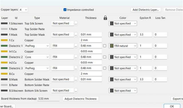
    This is the stack-up of our rigid sensor PCB. Also, we are planning to put the sensor directly inside the water. Please refer to the image below. 

  • Dear John,

    Aslo we tried using flex pcb of 35cm but in that also we put it outside the container when we add water just even 1 cm it gets saturated but when initially it is showing some positive results. In air it gives 6.7pF with the container walls. but inside container we add even 2 cm water is gives us value of 15.998pf but the RE is changing with the change in the water height like in air it gives 31pf but just with water is is decreasing to 2pf then going till 0.7pf

  • Sanjeet,

    Is the pipe orientation vertical as your picture shows, or is it laying horizontally when in use?

    Also, you may be able to overcome the saturation by adding an offset via the CAPDAC setting.
    In some cases, that can extend the max capacitance to ~110pF.

    Regards,
    John

  • Hi John,

    It is vertical. Yes we will check for that. But if is saturating like in between values, also like 12.8pf after adding capdac. Aslo In our 4 layer board. we are facing a issue of which I explained earlier in the previous comment Can you comment on that? 

    My question is can we make 4 4-layer rigid PCBs with, like the outer layer 2 layers just of fr4 epoxy no copper traces and nothing. so the sensor electrodes wont come in direct contact with the water, Aslo what thickness of PCB we require to make it working?

  • Sanjeet,

    We don't have a way to evaluate the PCB stack-up you showed earlier, so its hard to comment.

    The latest approach (4 4-layer rigid PCBs...) sounds like it has potential, but the details (thickness of PCB...) will depend upon the implementation, so giving detailed guidance is difficult. 

    The best approach would be to prototype the PCB and evaluate it.

    regards,
    John

  • Dear john,

    We have made a 4 layer PCB. but facing some layout and fabrication issue. Like still at Fr4 on top layer it is not working. 

  • Sanjeet,

    Can you share the layout (all layers) of your sensor PCB?

    Regards,
    John

  • Hi John,

    Please find the layout step file. fdc-capacitive-35cm.zip

  • Thank you Sanjeet.

    I'm having some problems with my SolidWorks, and will need to get support from IT.

    I will provide an update no later than COB on Monday.

    Regards,
    John

  • Sanjeet,

    Is it possible your sensor area is too big and results in too much capacitance? The sensors shown in the photos look pretty long.
    The nominal capacitance the FDC1004 can support is ±15pF. You can extend the measurement range to ~110pF with the CAPDAC. 

    Remember the ideal capacitor equation is ∈A/d where A is the sensor/plate area, d is the separation distance between the sensor and the ground plane, and ∈ is the permittivity of the medium. This equation will give a different result compared to the sensor suspended in air with no ground plane nearby.

    The liquid you want to measure is the medium (with some permittivity ∈) and the sensor area is A. If the sensor is immersed in the liquid, the 'd' may be extremely small, which could make the capacitance very large.

    What readings do you see if you place your sensor directly on a grounded metal sheet? 
    What do you see if you change the distance between the sensor and the conductive sheet?

    regards,
    John

  • Dear John,

    We want to detect the 30 cm length. so it is 30 cm long.   we want to monitor the water level height. so the dielcttic of water is 80 it is always high.  we haven,t tried directly on the grounded metal sheet. We will check that. we checked with water. even using the capdac it is showing the the same saturation . 

  • Thank you Sanjeet.

    I should have asked this right away, but is the liquid to be measured just pure water, or are there any additives?
    The FDC1004 does fine if the liquid is non-conductive, but can struggle if the liquid medium is conductive.
    For example, distilled water has a high resistivity, and experiments have shown the FDC1004 does fine at estimating liquid level.
    But if you add something like salt, it can be conductive, making capacitive-based measurements difficult.

    Also, thanks for sensor info.
    I tried some simple calculations based on the ideal parallel-plate capacitor equation C = εoεrA/d.
    It may not directly apply to your sensors, but it could give us some indication of the larger factors in play.

    If we assume:
    εo = 8.85x10⁻¹² F/m
    εr = 80
    A = L x W = 30cm x 0.5cm = 15cm2
    d = 0.1cm (assuming this is the thickness of the flex layer between the water and copper sensor)

    The (very approximate) capacitance based on the equation above is C = (8.85x10⁻¹² )⋅80⋅15⋅10-4/10-3 ≈ 1nF, which is pretty big compared to the max capacitance supported by the FDC1004. I'm guessing the water's close proximity to the sensor (d = 1mm) may be a contributing factor. If this turns out to be the case. would it be possible to increase d by adding an electrically neutral coating over the sensor flex?

    Regards,
    John