AWR6843ISK: AWR6843ISK UART direct connection

Part Number: AWR6843ISK
Other Parts Discussed in Thread: AWR6843, LP-XDS110

Tool/software:

Hi Ti team,

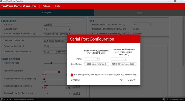
I am using AWR6843ISK EVM standalone card ,The board is connected using USB cable from PC and able to run with TI provided application(ex:outofbox demo) and visualize the point cloud data. 

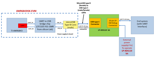
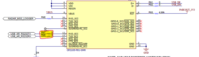
As per my understanding there is an "I/O Controller Interface IC USB to Dual UART bridge-CP2105-F01-GMR from silicon LAB (" which takes care of USB to UART data interfaces), so we are able to interface and use with UART ports at our PC with configuring necessary driver.

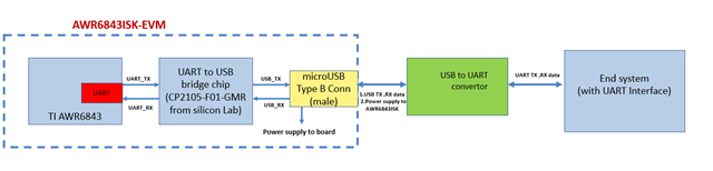
My requirement is to directly connect the UART(TX,RX) signals from AWR6843ISK EVM standalone card to my system(i do not want to connect Via USB Cable connection to PC and board )  and check the point cloud data .

My question:

1. can you confirm ,how i can connect it directly to UART ? is there any existing provision to do it?

2. and also confirm what voltage standards/ level will be getting from UART ,so i can ensure necessary Voltage standards are maintained at my system side too.

3. As per my understanding ,power supply to the AWR6843ISK EVM standalone card also supplied via USB connector only, so if i am connecting UART directly without USB cable connection,

   in this case ,how to supply the power to the AWR6843ISK EVM standalone card  to work and also confirm Power supply voltage and Current rating required ?

Note: My requirement is to Run AWR6843ISK EVM standalone card alone (with out Integrating addon cards like  mmwavebooster card /DCA1000 card)  

regards,

Mani

  • Hi Mani,

    1. You can take off the highlighted zero-ohm resistances and bring out the UART RX and TX lines from that point.

    2. The voltage level for UART is 3.3V IO.

    3. You can still supply power using the USB connector after disconnecting the USB to UART converter.

    Regards,

    Sreedeep

  • hi sreedeep,

     thanks for your reply.

    i have few more clarification,

    1. since SMD components are used ,it might be difficult to remove those resistor and make the direct connection for UART RX and TX,

    can you confirm ,is there any Jumper pins or test points or connectors (these connections are brought out ),so i can directly use it ?

    2. I can see from the image shared ,i see two set of com ports (standard ,enhanced ) are available on CP2105-F01-GMR

          set 1(enhanced)  RXD_ECI,TXD_ECI (pin 12,pin13) 

          set 2(standard  RXD_SCI,TXD_SCI (pin 20,pin21)

    and we also set the com ports at the applications before  running (TI mm wave visualizer app serial port screenshot attached for your reference-which is used to visualize the output point cloud data of TI outofbox demo )

    a)can you confirm ,how many UARTS are there at AWR6843 device ,

    b)if i have to make direct access to UART TX and RX, is it sufficient to make changes suggested by you on previous reply or do i need to do changes for any additional UART(please confirm)?

    regards,

    Mani 

  • Hi Mani,

    The UART lines haven't been brought out to any test point, jumper or connector. You have to remove resistors as I mentioned earlier to bring the UART lines out. 

    There is only one set of UART lines in AWR6843, and this can be connected the way I mentioned.

    Regards,

    Sreedeep

  • Hi sreedeep,

     i have additional question here.

    As you suggested ,i take off the highlighted zero-ohm resistances and bring out the UART RX and TX lines and connect with my system.

    and but I am not able to supply power using the USB connector (since my system is not PC).

    my question:

    1. in this case ,can you confirm how to provide required power supply to the AWR6843 ISK board to operated?

    2. if i can supply directly from external supply, can you confirm is there any Jumper pins or test points or connectors to supply it ?

    3. My requirement is to connect the UART(TX,RX) signals from AWR6843ISK EVM standalone card to my end system(i do not want to connect Via USB Cable connection to PC and board )  ,is there any converter card can be used to meet the above requirement without doing much changes, you can suggest(if your aware)?

    regards,

    Mani

  • Hi Mani,

    You can solder out the pad of L9 and provide the 5V input supply. There are no test points or jumper pins to connect to for power supply. Which converter card do you require?

    Regards,

    Sreedeep

  • hi sreedeep,

    thanks for your reply.

    Looking for USB to UART converter (green color box in the attached screenshot)

     '

    regards,

    mani 

  • Hi Mani,

    You can use LP-XDS110 board (LP-XDS110 Development kit | TI.com) as a USB to UART converter if it's just for testing purpose. Or you can use CP2105-F01-GMR itself externally for USB to UART conversion.

    Regards,

    Sreedeep 

  • Hi sreedeep,

     thanks for your reply. 

    i have gone through USB to UART converter details shared by you.

    i have attached updated interface diagram with LP-XDS110 development kit for your reference.

    I have few clarification:

    1.as per my understating, i need to provide external power supply to run LP-XDS110 development kit  as shown in above diagram,

         a.is my understanding correct? 

         b. does LP-XDS110 development kit get any internal power supply via USB C type connector also to run?


    2. Can you confirm, the connector type (female/male) of USB C type on LP-XDS110 development kit?

    3. Can you confirm, the required power supply to run the AWR6843ISK EVM is supplied from LP-XDS110 development kit via USB C type Connector or not?

    4.please confirm, the attached interface diagram with LP-XDS110 development kit will work without issue or do i need to do any additional thinks?

    regards,

    Mani