This thread has been locked.

If you have a related question, please click the "Ask a related question" button in the top right corner. The newly created question will be automatically linked to this question.

Explaining Nonlinearity Specification of a CMOS Analog Output Temperature Sensor

Other Parts Discussed in Thread: TMP20

In TIs datasheets, the nonlinearity of a CMOS process temperature sensor is specified as a percentage.  I’ve read the notes explaining that “Nonlinearity is the deviation of the calculated output voltage from the best fit straight line.” but still do not understand exactly how this value is calculated. 

Can you please explicitly show me how it is calculated? 

Can you also explain to me how it relates to the temperature error curves? (See Figure 7 of TMP20 part in “SBOS466”)

In the end, I would like to compare nonlinearity between CMOS and Bipolar processes which are not specified the same way.

Thank you,

E

  • Hello Eric,

    Thanks for posting your questions on Non linearity aspect of TMP20, we will get back to you on this soon,

    Regards,

    Abhi

  • Hi Eric,

    I will start explaining how we calculate the nonlinearity.

    Looking on Page 7 of the Datasheet you find the nonlinear transfer function of the TMP20:

    Vout nonlinear= (–3.88×10⁻⁶×T2) + (–1.15×10⁻²×T) + 1.8639V


    When you now calculate this from -20°C to + 80°C (the range which is used for the nonlinearity number in the datasheet) you can extrapolate a linear slope which goes from the minimum value to the maximum value.  You will get this formula:

    Vout linear= -0.01173 x T + 1.8577

    Plotting those two lines in one graph will look something like this:

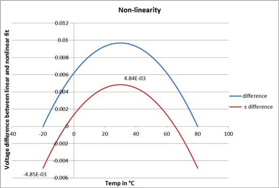
    Since the device has a good linearity you can’t see a big difference between those two lines. In the next Graph I will now subtract the linear line (red) from the nonlinear line (blue) and just display the difference between those two values.

    The blue line with the name “difference” displays: “Vout nonlinear” – “Vout linear”. To calculate the nonlinearity error I now put the line right between plus and minus and called it “± difference”. See attached Excel sheet for exact calculation. This line has the same positive and negative error. We can now calculate the nonlinearity with this formula:

    Nonlinearity = Maximum nonlinearity / full scale = 4.85e-3V / 1.17V x 100% = 0.41%

    The 4.85e-3 is the maximum value of the red “± difference” line. The 1.17V are the full scale of voltages we use going from 2.092V to 0.919V (see first graph).

    Figure 7 in the datasheet now shows the spread of nonlinearity over the full temperature range measured for 39 different devices.

    Did this answer your question? If there is still something unclear please don’t hesitate to ask.

    Best Regards,

    Simon

    Mail: s-forstner@ti.com

    7317.TMP20_Nonlinearity.xlsx

  • Excellent explanation!! Thank you, E