This thread has been locked.

If you have a related question, please click the "Ask a related question" button in the top right corner. The newly created question will be automatically linked to this question.

LMP91300 Rp Value Variation after setting DET_H and DET_L

Other Parts Discussed in Thread: LMP91300

I'm working with LMP91300 in order to detect a steel target between 0-3mm range.  While using the evaluation board to program the DET_H and DET_L thresholds I took samples at 3mm for the DET_H and 3.3mm for the DET_L. 

(from 1000 samples)
DET_H mean was 17027, Std Dev was 11. 74, Delta 73

DET_L mean was 16921, Std Dev 12.65, Delta 78

These values where written into the DET_H and DET_L FNL registers 0x73-0x76.

I then moved the target to 0mm from the sensor and started moving it away to verify that the target was detected properly within the 0-3mm range.  When I reached 2.84mm the output started to flicker.  I stopped and took 100 samples to see if the Rp value was varying between the DET_H and DET_L values and causing the flicker and I got this as my readings with 100 samples:

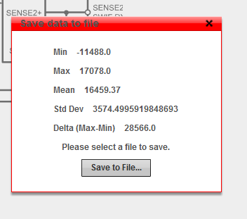
I've checked the other registers in the LMP and the values are all as we programmed them when we took the sample readings. Is there anyway writing the 0x73-0x76 registers could have caused this?  If not then what are some possible explanations for this?

Thanks,

Cam

  • Hi Cam,

    Please let me look into this matter for you. I will try to have a response in a day.

    Regards,

    ChrisO
  • HI Cam,

    If you are working with a part that has not had values burned into the memory you should be using registers 0x00 to 0x72. The detection registers that you should be using are the registers at 0x66 to 0x69. See the section on page 17 of the datasheet.

    The values that you recorded when you were taking the 1000 samples seem noisy.
    >>DET_H mean was 17027, Std Dev was 11. 74, Delta 73
    >>DET_L mean was 16921, Std Dev 12.65, Delta 78

    Could you tell me the values that you have in the registers 0x6E to 0x72? Also how did you determine the values of RP_MAX and RP_MIN of your LC tank? What frequency does the it oscillate at when there is no target close to the LC tank?

    Thanks,

    Mike
  • Hi Mike,


    There where values previously written into the 0x73-0x76 so I was just over writing them.  Am I able to 0 them out and then use the 0x66-0x69 for my detection values while testing this setup?


    Here are the values from 0x6E to 0x72.

    0x6e 0x12
    0x6f 0xf5
    0x70 0x5a
    0x71 0x37
    0x72 0xa2

    The RP_MAX and RP_MIN values where determined following section 8.2.2.2 on the datasheet.

    The tank oscillates at 51K.

    Regards,

    Cam

  • Hi Cam,

    If you power cycle the LMP91300 the default values should be:

    0x6E 0x0E
    0x6F 0x14
    0x70 0x45
    0x71 0x1B
    0x72 0xA2

    The part uses either registers 0x66 to 0x69, 0x71, 0x72 or 0x73 to 0x78 depending on the burn state of the device. Can you read register 0x7E (located on the CAT4 tab in the software) so that we can determine if the part was burned?

    Mike
  • Hi Mike,


    0x7E is 0x23

    Regards,

    Cam

  • Hi Cam,

    That code says that the LMP91300 has been burned, all registers between 0x00 and 0x78. This means that option 3 on page 17 of the datasheet applies:
    3. Values have been burned into the LMP91300 memory using burn request 0x10 or 0x20.
    (a) When powered on the LMP91300 will use the burned values in registers 0x00-0x5D, 0x6A-0x70 and 0x73-0x78.
    (b) If a value is written to an INIT register (0x66-0x69, 0x71-0x72) it will be ignored and the corresponding FNL register (0x73-0x78) will be used.
    (c) If a value is written to a FNL register (0x73-0x78) the LMP91300 will use the written value instead of the burned value.
    (d) If the LMP91300 is powered off and then back on the LMP91300 will use the burned values in registers
    0x00-0x5D, 0x6A-0x70 and 0x73-0x78.

    This explains why the power on values do not match the datasheet default values.

    Looking at the values that are in registers 0x6E to 0x72 that you mentioned above, the values in registers 0x6E and 0x6F are not good.

    The value of 0x12 in register 0x6E sets RP_MAX at 5387 which is very low.

    The value of 0x5F in register 0x6F sets PADC_TIMEC to 111b which can cause the part to be unstable. It is better to set this to 001b as recommended in the datasheet. RP_MIN is set to 10101b (21) which is not an valid value.

    Mike
  • Hi Mike,


    From looking at the Register Setting/RP table found in section 7.6 does the value of 0x12 in 0x6E not set my RP_MAX to 27704 instead of 5387? See table below.

    Can you also please explain why you stated that a value of 10101b is invalid as when converted it would be 0x15 which is listed on the table above as a valid value.

    If the value of 0x15 for RP_min is used and the PADC_TIMEC is set to 001 then the correct value for 0x6F would be 0x35 correct?

  • Hi Cam,

    Sorry about that, I got it mixed up in the registers I was looking at.

    With the values you have RP_MAX = 27704 and RP_MIN = 12120. PADC is set to 111 which is not a good value. It should be set to 001.

    After changing PADC when you have the target at 3mm are the results less noisy? You can also try different combinations of setting RP_MIN to 0x16 or 0x17 and/or RP_MAX to 0x11 or 0x10 to see if it gets less noisy.

    Mike
  • Hi Mike,

    I had thought about that and have been working with the unit adjusting my RP_MIN/MAX values to see if it got any less noisy.

    The best results I've gotten are a delta of 66 and a standard deviation of 12 which still seems awfully noisy to me but, I was able to set the DET_H and DET_L.  I just have a much larger hysteresis than we wanted.   3mm is the switch on point(17684) and 3.3mm us the switch off(17591).  This was based on the data shown in the attached file.  I then set the unit at 2.75mm away from the target and was moving out to the turn off point of 3.3 to verify that my settings worked, at 2.93mm the units output started flickering and I took a continuous 1000 sample reading which I graphed on the second graph below.  Any ideas as to what would cause the Rp value to go deviate by a reading of 5000?

    3mm_11_15-GraphData.xlsx

  • Hi Cameron,

    Can you check the signal on the CFB pin? The CFB signal amplitude should be 1Vpp and is set by the CF cap. This is described in section 8.2.2.4 on page 30 of the datasheet. If the amplitude of the signal on CFB becomes too large it can cause reading like you are seeing. When I am looking at this signal I set up the scope like shown in Figure 21 and then stop the scope acquisition many times to find an accurate maximum since the signal is varying its amplitude.

    Mike
  • Hi Michael,

    I was finally able to check the amplitude of the signal on the CFB pin. See the attached, the CF cap is 150pF.

    So to get the 1Vpp the CF cap should be a value of 450pF.

  • Hi Cameron,

    Looking at your scope photo, is the top trace the CFB pin and the bottom trace the INA or INB pin?  What is the V/div for each trace?

    Can you zoom in your signal and see if it looks different?  The time base may be too long and hiding the actual shape of the signal.  It should look like the signal

    in Figure 21 of the datasheet but your signal appears to be flat on the bottom. 

    Mike

  • HI Mike,

    Yes the top trace if the CFB pin, the bottom trace is INB. The CFB is set for 2V/div while INB is set for 1V/div.

    I'm fairly certain it was flat on the bottom, but I will double check about the CFB signal being flat on the bottom when I'm in the office tomorrow. What does it mean if it is flat on the bottom?

    Some other information which may apply is:
    -LC tank consists on 6mH coil and ferrite and 2.2nF cap, engineering firm says it oscillates at approx 52K. I calculated 47K
    -readings shown are taken while in the housing which is made from 316 SS which completely surrounds the coil
    -the sensing face of the housing is 0.3mm thick 316 SS

    Is it possible for this chip to function under the conditions above?
  • Hi Cameron,

    Yes, it shouldn't be flat on the bottom.  See Figure 21 in the datasheet.  Your signal is about 3V which may be causing the signal to bottom out at the low end.  Your calculation of 450pf is a good value to try.  Remember to do this while there is no target close to the LC tank.  This is because this signal is maximum when there is no target. 

    The part should work down to 5kHz oscillation so your LC tank oscillating at about 50kHz should be ok.  

    Mike

  • HI Mike,

    One other question will the fact that there is a 0.3mm thick 316 Stainless Steel face in front of the coil cause any issues? Like the flat bottom on the CF or is that going to be strictly related to the value of the capacitor?

    Regards,

    Cam

  • Hi Cameron,


    The signal on the CFB pin is maximum when there is no metal target close to the coil.  Having the metal in front of the coil will make the signal smaller. 

    A problem with having metal in front of the coil is that it is harder to detect another piece of metal that is further away from the coil.  The LMP91300 works by detecting the losses caused by the eddy currents in the metal that is in front of the coil.  If you have a metal face in front of the coil, most of the losses the LMP91300 will be able to detect is what is lost through the eddy currents in the metal face.  The losses caused by the small amount of the magnetic field that gets past the face and is able to get to the external metal will not be much and so will make the LMP91300 not very efficient at detecting the external metal.

    Mike

  • Hi Michael,

    Thank you. So even if we load the board and coil into the body and tune the Rp Values and CF cap it likely won't work. oes TI have another chip which is able to detect through a metal face?  

    Regards,

    Cam

  • Hi Cam,

    All of the inductive sensors work on the same principles, so it is difficult to sense a metal through another metal.  It can be done though, although not with very good resolution of the distance of the target to the sensor.  Since your metal is so thin, it might be possible, if you use a lower frequency LC tank.  It will take some experimenting though to find the correct frequency for the LC tank.

    Mike