This thread has been locked.

If you have a related question, please click the "Ask a related question" button in the top right corner. The newly created question will be automatically linked to this question.

TDC1000 for distance measurement

Other Parts Discussed in Thread: TDC1000

Hello Team,

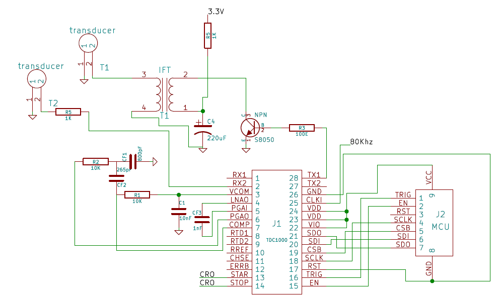
I am using the below transducer with the TDC1000. Since it has a higher input peak to peak voltage requirement I have used Intermediate frequency transformer and boosted the 40khz bursts incoming from the micro controller. Max Vp-p of this sensor is 60. The customer requires a maximum of around 3-5m with ± 2cm accuracy and a single transducer to act as both transmitter and receiver . I have used the chip in mode-1 configuration. Am I missing something? 


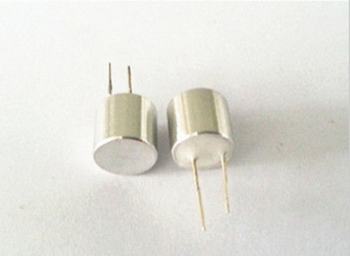
Below are the transducer specs,

Diameter: 10 mm
Center Rated Frequency: 40 KHz
Sound Pressure Level (at 10V): ≥ 117 dB
Receiver Sensitivity (at 40KHz): ≥ -65 dB
Capacitance: 2400pF ± 25%
Maximum Input Voltage: 60Vp-p
Directivity: 60°±15° (-6dB) 
Operating Temperature: -20°C~+70°C 
Storage Temperature: -40°C~+85°C

  • Please check this discussion thread

    e2e.ti.com/.../1430369

    Thanks.
  • Thanks for your reply.

    This is how I am configuring the registers.

    config_0 - 0x08

    config_1 - 0x41

    config_2 - 0x00

    config_3 - 0x03

    config_4 - 0x5F

    config_5 - 0xE4

    config_6 - 0x00

    config_7 - 0x00

    config_8 - 0x43

    config_9 - 0x00

    This is circuit setup,

    I have connected the START and STOP to CRO. I am triggering the TDC1000 every one sec. I can see the start pulse being transmitted but I dint receive any stop pulse and there is no pulse even in the RX2 pin. Please suggest If there are any errors in the configuration or the circuit.

  • a) You mention mode1 configuration and your schematic also assumes two transducers in pitch-catch configuration. Please check CONFIG2 register initialization. It is set as 0x00 which corresponds to mode0.

    b) As shown in the TDC1000-TDC7200EVM schematic, we use a buffer and observe the echo on the COMPIN terminal. At evaluation time, you have to continuously trigger TDC1000 every 200ms or so and change the threshold/gain and other register settings to see the echo and the transducer behavior with TDC1000. The TDC1000-TDC7200EVM and GUI would help on this evaluation than a custom board.

    c) When using mode1, try with single echo configuration (CONFIG4 register = 0x1F)

    d) ERRB is open drain (needs a 10k pull up)

    e) I didn't verify your receive filter for 40kHz but assume you would have looked at the suggestions in the link above. You can look at the following app note Section 2.2 to understand the receive signal path and the external components required.
    www.ti.com/.../snaa284a.pdf

    Thanks,
    Vishy
  • This posting on short distance measurements in AIR would also be of interest to you

    e2e.ti.com/.../498792

    Thanks.
  • Sir i am going with same circuit what vipin chandra posted. But that is not properly boosting the tx signal power. Please guide me how to overcome from that problem.