This thread has been locked.

If you have a related question, please click the "Ask a related question" button in the top right corner. The newly created question will be automatically linked to this question.

Using TDC1000-TDC7200EVm unable to get proper Reading.

Other Parts Discussed in Thread: TDC1000, TDC7200

https://e2e.ti.com/support/sensor/ultrasonic/f/991/t/539200

Hi,

As you said, i have attached have glued my  transducer to the bottom surface of my plastic beaker.

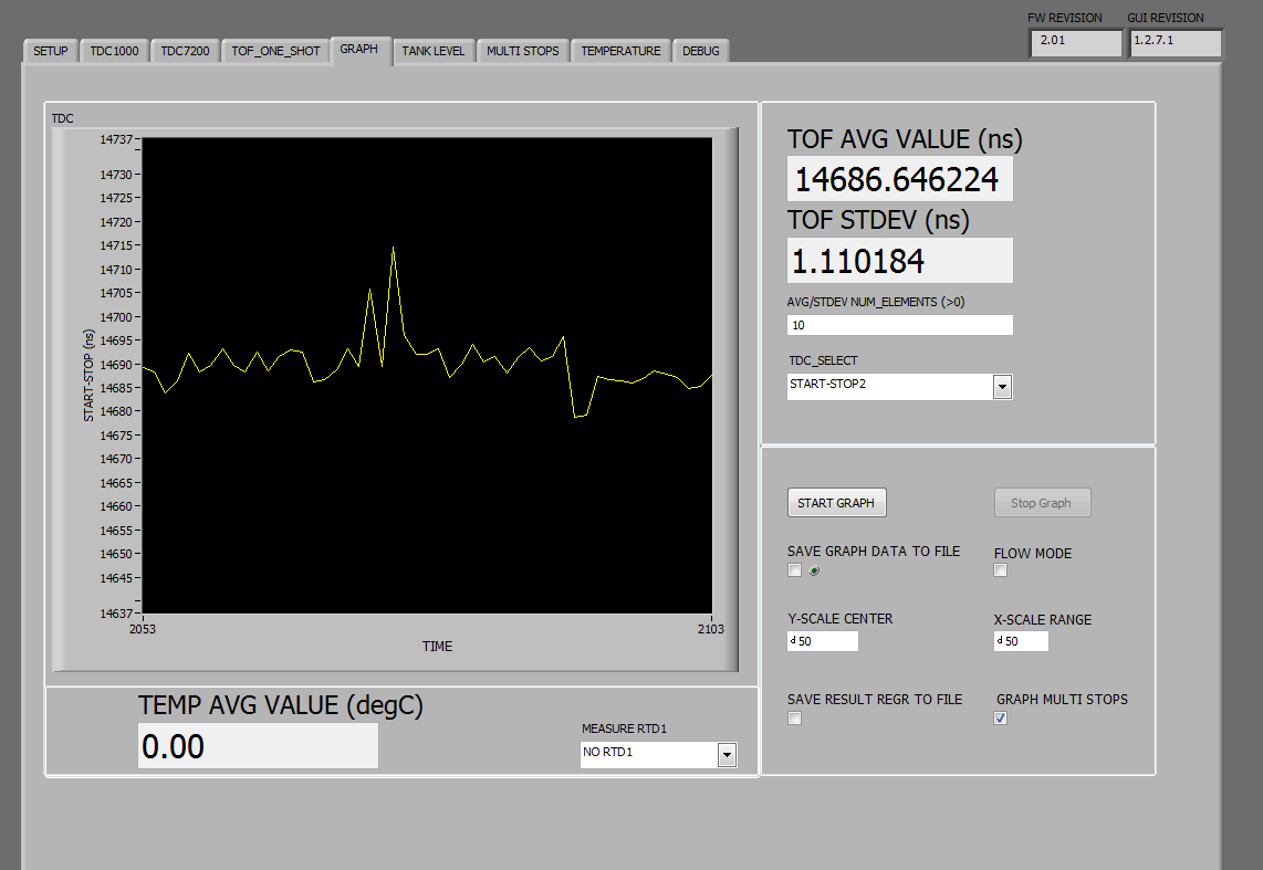
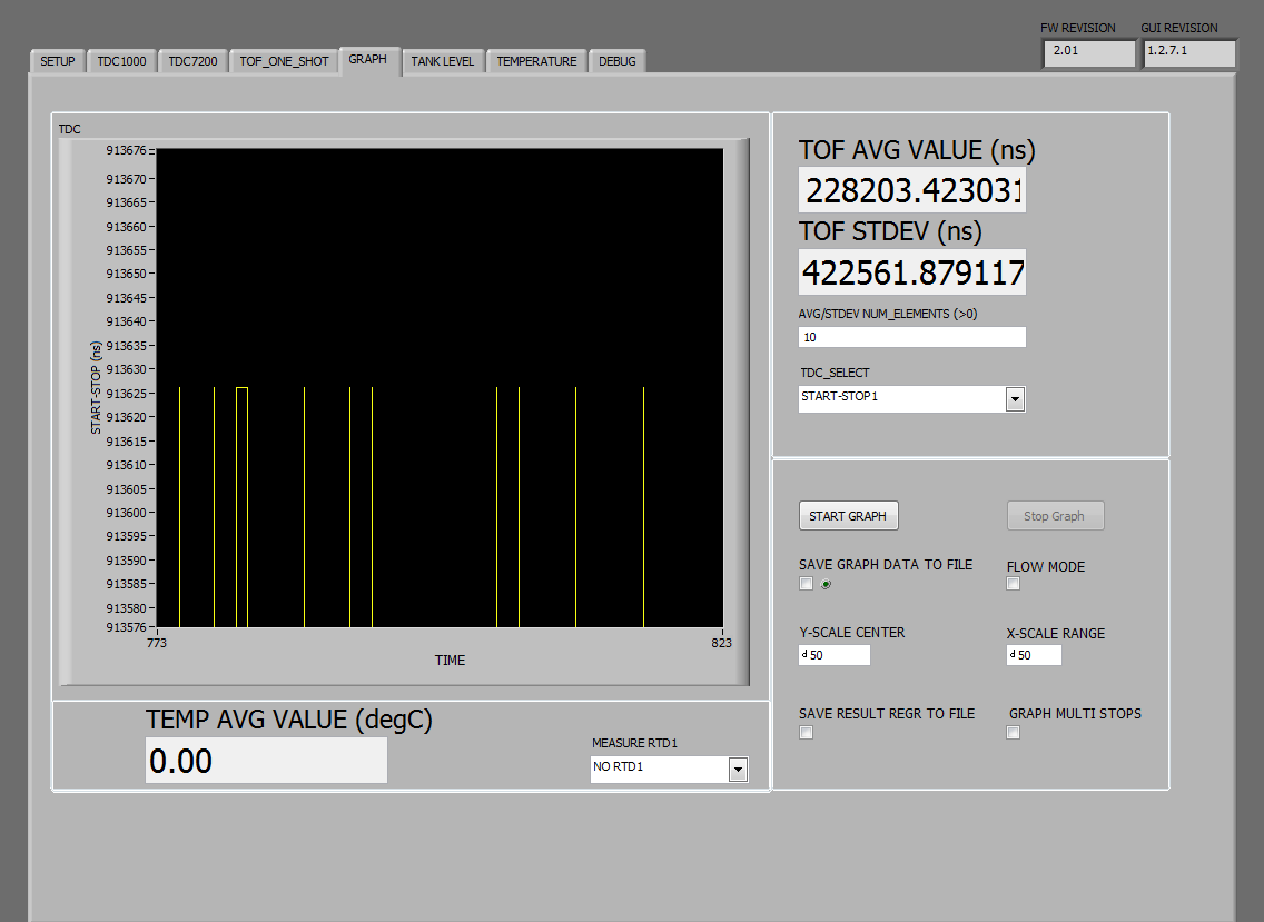
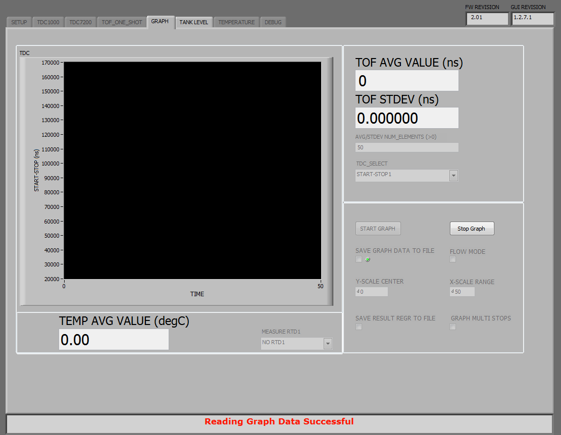
1) It is still not giving me proper reading and the readings are different most of the time(mostly a very small value) .

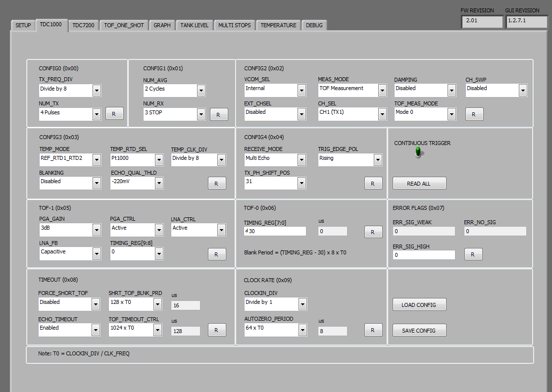
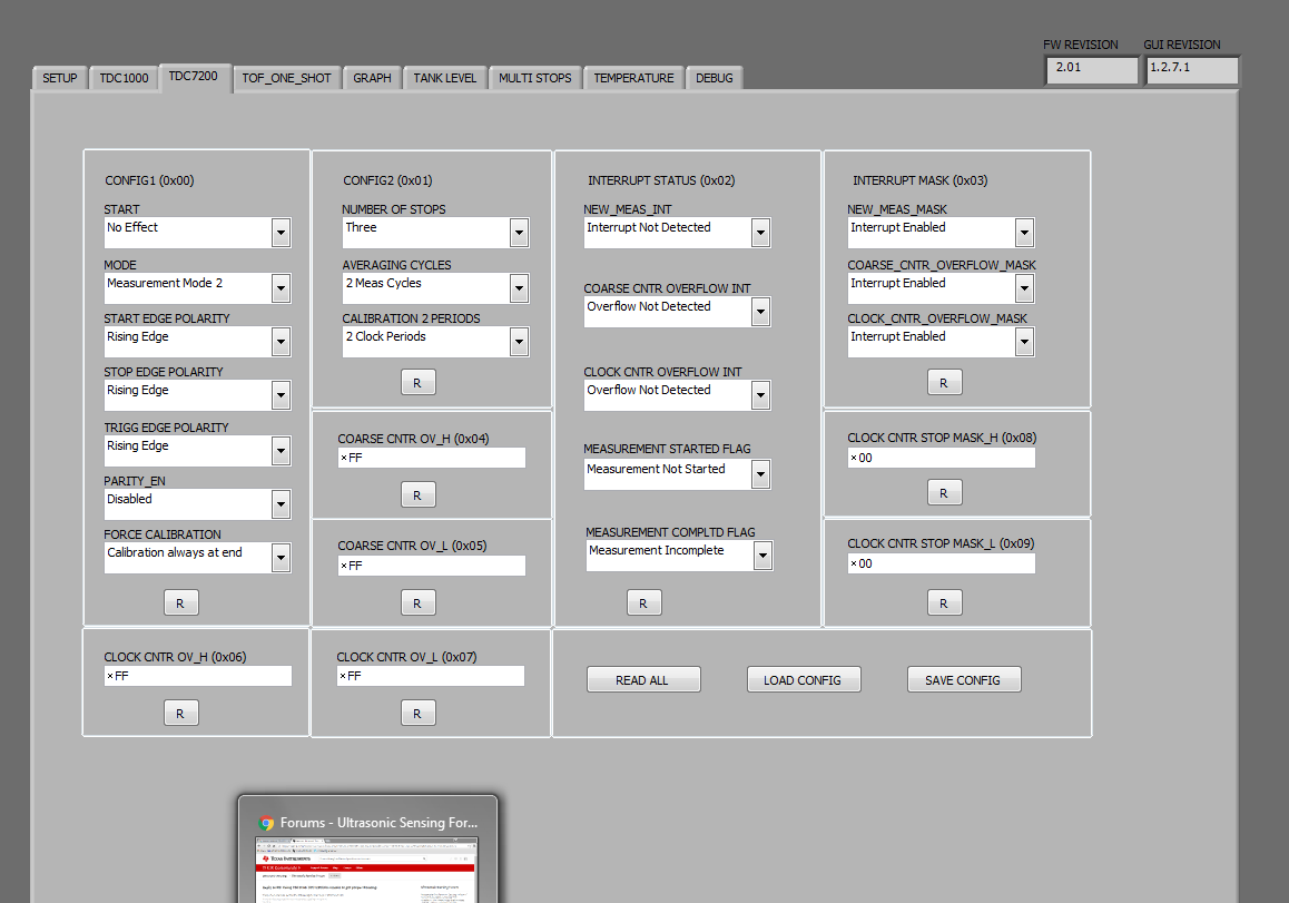
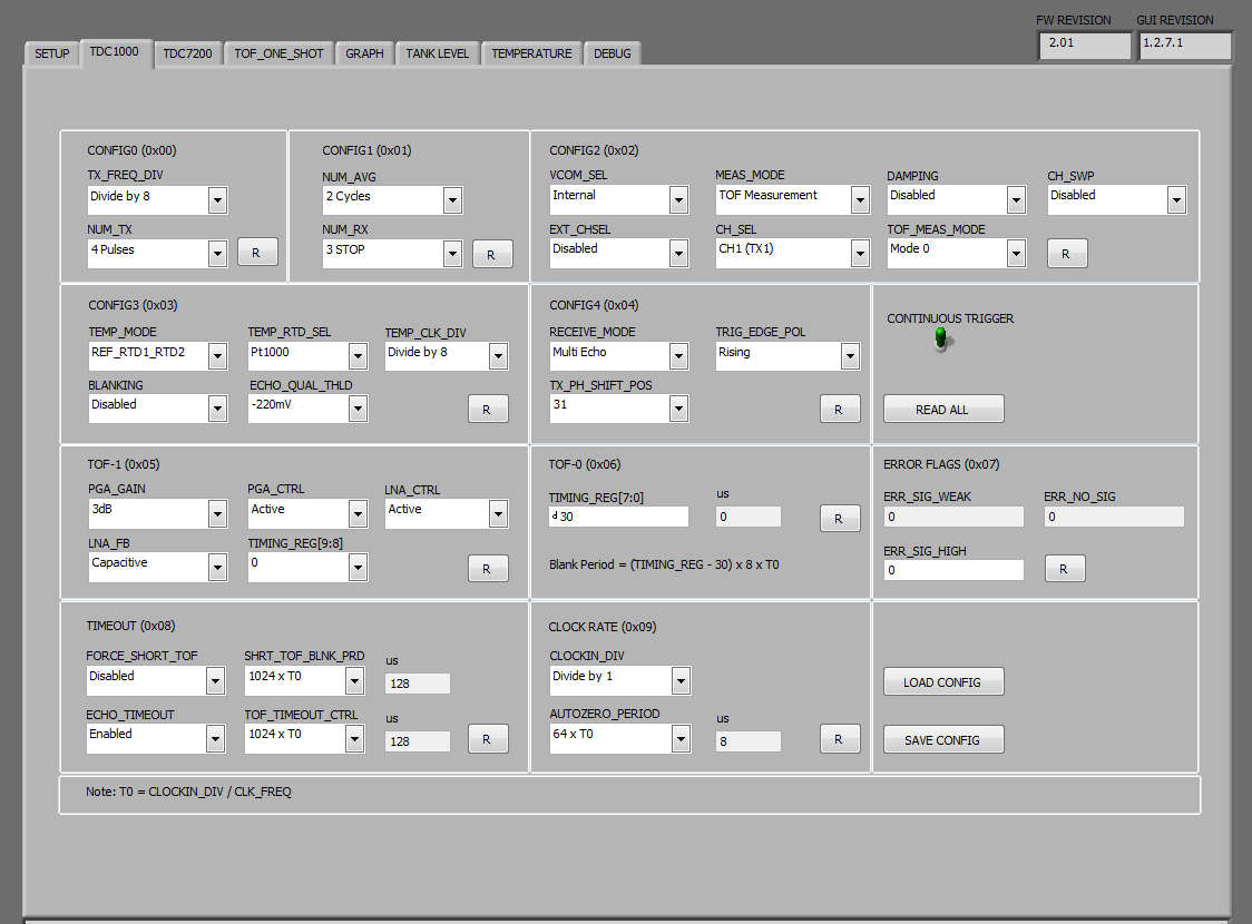
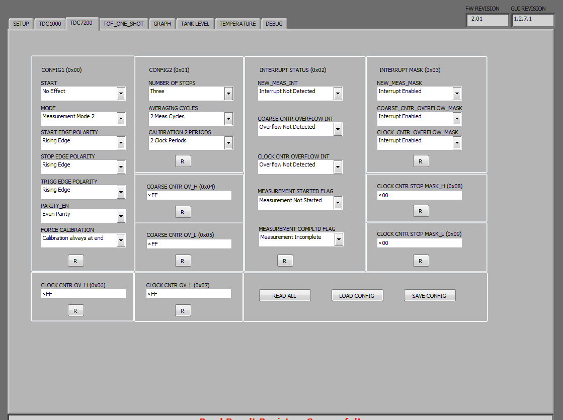
2) Under parity enable condition it is giving me a very high value , in addition to that the clock_count1  bar is showing a zero  and it shows a huge value in time 1 register (in measurement mode 2) which should not be so.

3) water level is not increasing  when i add water.

case 1) At parity disabled

WHEN PARiTY WAS ENABLED THE GRAPHS AND SETTINGS WERE AS BELOW

Kindly help me with this.

Thank you ,

Noble.

  • Noble,

    a)  I enclose below a config file for level measurement. You can use this config file as a starting point for experimenting. From the GUI, you can load this config file when you start to debug. It automatically sets up all the parameters and registers for  you. If you modify something, you can save and update the file as well. You do config file load and save operations by using "Load Config" and "Save Config" buttons of the TDC1000 (or TDC7200) tab of the GUI.

    7725.RegisterFiles-TDC1000_7200_level_cells_saleskit_2_2015_1271GUI.txt
    TDC1000_Config0                         41
    TDC1000_Config1                         41
    TDC1000_Config2                         00
    TDC1000_Config3                         04
    TDC1000_Config4                         5F
    TDC1000_TOF-1                           03
    TDC1000_TOF-0                           FF
    TDC1000_Error_Flags                     00
    TDC1000_Timeout                         23
    TDC1000_Clock_Rate                      00
    TDC1000_Conts_Trigger                   01
    TDC7200_Config1                         02
    TDC7200_Config2                         40
    TDC7200_Interrupt_Status                07
    TDC7200_Interrupt_Mask                  07
    TDC7200_Coarse_Cntr_Ov_H                FF
    TDC7200_Coarse_Cntr_Ov_L                FF
    TDC7200_Clock_Cntr_Ov_H                 FF
    TDC7200_Clock_Cntr_Ov_L                 FF
    TDC7200_Clock_Cntr_Stop_Mask_H          00
    TDC7200_Clock_Cntr_Stop_Mask_L          00
    TRIGGER_UPDATE_FREQ                     0004
    TDC_AVG/STDEV_NUM_ELEMS                 0032
    SAVE_GRAPH_DATA_TO_FILE                 00
    FLOW_MODE_SELECT                        00
    Y-SCALE_CENTER                          0000
    X-SCALE_RANGE                           0032
    MEASURE_RTD1                            00
    SAVE_RESULT_REGR_TO_FILE                00
    GRAPH_MULTI_STOPS                       00
    TDC_SELECT                              00
    TEMP_RTD_SELECT                         00
    TEMP_RTD_MODE                           01
    TEMP_AVG/STDEV_NUM_ELEMS                000A
    SAVE_TEMP_DATA                          00
    GRAPH_YMAX_DATA                         0000000000029810
    GRAPH_YMIN_DATA                         0000000000004E20
    TDC1000-HV_DRV_EN1                      00
    TDC1000-HV_DRV_EN2                      00
    HV_DRV_EN1_Period                       001E
    HV_DRV_EN2_Period                       001E
    ENABLE_POWER_CYCLE                      00
    CLK_FREQ_(1-16MHz)                      8.000000
    CLK_SOURCE_SEL                          00
    CPU_CLK_FREQ                            05
    CPU_CLK_EN                              00
    TDC1000-HV_BST_PWR_EN                   00
    HV_BST_PWR_EN_Period                    0000
    FWD2REV_FLOW_DELAY                      0000
    TDC1000-IMPE_MATCH_EN                   00
    ENABLE_UART_STREAM                      00
    ENABLE_MSP430TIMER_TDC                  00

    b) Keep water level fixed to say about 50us TOF. Use the equation TOF = 2 x D / C, where C is the speed of sound of sound in water (1480m/s), to find the corresponding level D. As explained in the app note I referred to observe if you are receiving a proper echo at 50us from the start pulse. You can observe START, STOP and echo pulses at TP5, TP6, and COMP_IN terminals and debug your setup.

    c) Pls review TDC1000 and TDC7200 data sheet for details of the register settings and their correct selection for level measurement.

    d) Also, I assume you have taken care to glue the transducer properly.  FYI, in app note SNA266, CYA is to ensure strong connection between the face of the transducer and the tank wall. Also, its low compressibility ensures there is no acoustic dampening. Whereas the glue, that is applied around the transducer circumference and backside, is for acoustic dampening (due to its flexibility) and wire strain relief. So the glue, if applied on the transducer frontside, can cause performance degradation and you may not see any echo.

    e) You can also see this posting for additional reference

    Thanks,

    Vishy

  • Thank you Vishy,

     a) I have mounted it as per the direction in the application note. 

    b)  when i tried using the configuration you suggested , I found no change in graph as if the echo voltage was not qualifying. 

        As per the stated configuration the echo threshold is  -220 upon increasing the threshold value to  -125  I got the graph which was still an incorrect one 
      , I even got a similar graph by increasing the gain value. 

       Please help me with this. 

  • The best way to debug is to observe the signals at the start, stop and comp_in test points. No need to try the graph at this time. Make sure "Continuous trigger" switch is green in TDC1000 tab and check if you are seeing properly the number of TX pulses selected (J5.10), start, stop and comp_in signals. Make sure transducer is connected at TX1 and not TX2.
    Thanks,
    Vishy
  • Not recieving the comp_in pulse or stop Pulse .  i receive only when I increase the PGA gain or by  bringing the negative threshold near to zero.


  • Thank you Vishy for the help,

             Today I found that upon increasing the  number of TX pulses I am getting a false echo I assume that  it is due to ringing .
    How do I know more about ringing effect and also want to know how does damping (increasing the width of the last pulse )
    reduce of compensate the ringing effect. 

    Thank You, 
    Noble.

  • There are a number of TDC1000 related app notes, DS, and User guides for you to refer here

    www.ti.com/.../technicaldocuments

    I suggest you use a scope and observe START, STOP, COMP_IN signals and TX pulses (J5.10).

    Thanks,
    Vishy
  • hey Vishy,
    got the result it was the issue of our transducer I got along with the kit . very sorry for the inconvenience and
    thank you for all the pain you took to help nothing has gone in vain it has helped me understand more about the kit and the application .

    once again thanks a lot.