This thread has been locked.

If you have a related question, please click the "Ask a related question" button in the top right corner. The newly created question will be automatically linked to this question.

IWR1443BOOST: what is the sample rate suppose to use?

Part Number: IWR1443BOOST
Other Parts Discussed in Thread: IWR1443

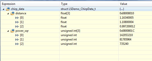
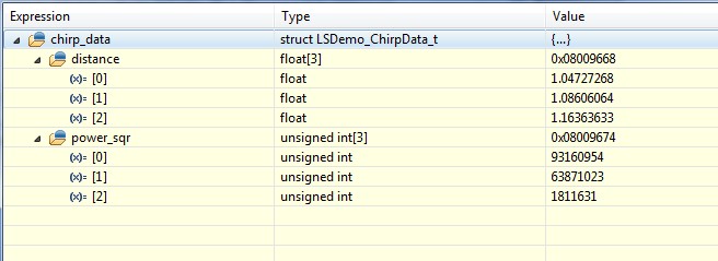
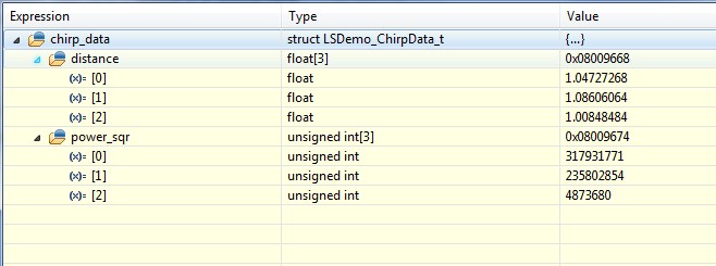
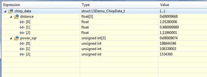
In the level_sense_demo project, if I set the "sample_rate" to 7.93 MSPS (from mmWave sensing estimate), all the measured the distances are zero, dis0=0, dis1=0, dis2=0,,if I change sample_rate to 8.2MSPS, the measured distances are dis0=3.4674 m, dis1=3.3512 m, dis2=3.5216 m, if I set sample_rate to 8.8 MSPS, dis0=3.2376 m, dis1=3.1240 m, dis2=3.1808 m, if further increase the sample_rate, the measured distance further reduce, the is the correct sample_rate, suppose to use? and what the relationship between the sample_rate and the distance? (normally high sample rate will get better accuracy, why it is not here, the maximum beat frequency is 7.14 MHz)

Thanks,

  • It sounds like you are changing parameters in a vacuum.  You must consider all the parameters of the chirp in order for it to work properly.

    I recommend that you set the level sense demo aside for now and use the mmw (out-of-box) demo along with the tools for it.  This will help you play with chirp configurations more quickly and easily. Once you've decided on a chirp, you can plug it into the level sense demo.

    Here are some materials that will help you create a valid chirp:

    This online tool lets you play with chirp parameters in realtime, and see their effect:

    https://dev.ti.com/gallery/view/1792614/mmWaveSensingEstimator/

    This document will explain the parameters and how they work together:

    Programming Chirp Parameters in TI Radar Devices

    Training videos on FMCW radars with specifics to mmWave devices, chirps, etc.

    Introduction to mmWave sensing: FMCW radars

    When you run the mmw demo on your 1443, the demo visualizer is here:

    https://dev.ti.com/gallery/view/534566/mmWave_Demo_Visualizer

  • Do you look at at my question close enough? all the chirp parameters are created by "mmWaveSensingEstimator", do you think "mmWaveSensingEstimator" not work?  The attachment is the chirp parameters files.

    ChirpParameters.docx

  • Here is my question again: if the Sampling Frequency Minimum (MSPS) from "mWaveSensingEstimator" is 7.93 MSPS, what the Sample_Rate should use in "level_sense_demo" CONFIG, why use Sample_Rate 7.93 MSPS all the measured distances are zero, why using the Sample_rate larger than 7.93, such as 8.2 MSPS, 8.8 MSPS etc. the measured distances are shorter. All other parameters are same as mWaveSensingEstimator's calculation. Does the "Sampling Frequency Minimum" from mmWaveSensingEstimator" means that is the minimum sample_ rate should use, any sample_rate high than this should work? I hope TI's mmWave expert could answer this question.
  • Typo error "mWaveSensingEstimator" in the post above means "mmWaveSensingEstimator"
  • Hello Feng,

    Can you please provide more information on how and why the Sampling Rate was changed.

    Maybe we are confusing the Sampling Rate of the Analog/RF end  with the  Update rate of the measured distance value.  (More on ADC Sampling Rate below)

    Typically we do not change such configuration values as a standalone change but instead we determine what the entire set of Chirp Parameters should be for a given Sensing requirement. Which is where the mmWave Visualizer Gui comes in.

    Sampling Frequency of ADC:

    The RF reflection received back from the object (level in this case) is converted to an Intermediate Frequency  (IF)and then converted to digital data by ADC inside the device. The conversion is done by sampling the IF data at "Sampling Frequency" which can be changed by setting the "Sampling Frequency" in the ADC configuration.

    I wonder if you are referring to this "Sampling Frequency" . - Please let us know.

    Changing this value alters sensing parameters:

    One way to see this is by trying various distance/range resolution values in  http://www.ti.com/tool/mmwave-sensing-estimator and noticing how the "Sampling Frequency" varies.

  • System only posted partial response. Appending the rest below:


    These parameters are explained in the Chirp design document and the Video link provided by Dave.


    As we change a certain sensing parameter (requirement) you will notice multiple Chirp Design Parameters (Configuration) change.


    In order to make the device sense as per new requirement the modified Configuration needs to be sent to the device.

    We would recommend trying these changes on the mmWave Out of Box demo which will allow you to see the changes in mmWave Visualizer Gui.


    Instead of changing an adhoc configuration value such as "ADC Sampling frequency" the entire Set of Chirp configurations should be regenerated based


    new sensing requirements and entire set should be resent to the device.


    Measurement Update Rate:


    The Out of Box demo performs a measurement update on the Visualizer GUI at end of every frame (which comprises of multiple chirps).

    This rate is set via the "Measurement Rate (Hz)" sensing parameter. If you wish to update the measurement rate then this is the parameter you should vary.


    Modifications to TI-Design Power Optimization for IWR1443 77GHz-Level Transmitter Reference Design :


    If you wish to modify the sensing parameters (requirements) in this design then the first option would be use one of the multiple available pre configured


    "DEMO_CONFIGx" .

    These can be set based on the "#define " in demo.h file in the TI-Design installation directory.


    If you wish to make a new configuration of you own then please follow the steps below:


    1. Determine your sensing requirements such as distance, resolution, (measurement) update rate etc

    2. Enter these values in the mmWave Estimator Tool.

    3. Generate the Chirp Configuration Values based on #2

    4. Add the generated confi as a new "DEMO_CONFIGx" in demo.h file

    5. Set the #define in demo.h file to use your custom config in #4.


    Hope this helps you get an orientation of what are the various ways to change the sensing parameters and what is the right flow to do so.


    Please let us know fi you have more questions on this.


    Thank you,

    Vaibhav
  • And the missing image referred in posts above:

  • First of all I want to point is the steps you mentioned are the steps that I used all the time, I mentioned many times the chirp parameters are calculated by mmWaveSensingEstimator, why are you confusing.
    The number one reason to change the "Sample_Rate" is the Sample_Rate" (7.93 MSPS from mmWaveSensingEstimator) is too close to the maximum beat frequency (7.14MHz also from mmWaveSensingEstimator), it is violet the sampling rule.
    Reason 2: using 7.93MSPS from mmWaveSenseEstimator with all the other parameters from ....SensingEstimator, all the measured distance are zeros. (do not know why?)(see the previous post attachment file for the chirp configuration and try it by yourself))
    reason 3: mmWaveSensingEstimator show "Sampling Frequency minimum (MSPS)", to me the "minimum" means if the Sampling Frequency larger than the minimum sampling frequency, the device should work and should give better accuracy, why it can not be changed.
    I also have question about you post "mmWaveSensingEstimator" parameters, if I use FFTsize 2048 and the Number of Sample per Chirp larger than 1000, the measured distance also all zeros, you also try to use FFT size 2048, do you load these parameters to your boards and to see if they work?
  • Hello Feng,

    Good to know that you have already used the Estimator tool for creating the chirp parameters based on the sensing needs.

    1) & 2) Please send us the configuration you have generated and tried via Estimator tool. "Save Config" option should allow that.
    That way we can debug the exact configuration you are trying out at your end.

    3) Keeping everything else the same and modifying the "Sampling Frequency" (of ADC) should not necessarily mean higher accuracy. Higher sampling frequencies enable higher Intermediate Frequency sampling which could help with higher distances.
    We do not expect it to zero out the measurements either, so debug from #1, #2 should help us figure out what is going on here.

    Regarding FFT size:
    The current processing chain does not support FFT sizes more than 1024 samples as the Hardware Accelerator of IWR1443 supports 1024 as maximum FFT size.
    FFT size is set based on number of Samples options to the nearest (higher) power of 2.
    How were you trying to set the FFT size option in your case?

    Thank you,
    Vaibhav
  • 1050.ChirpParameters.docx1 &2 Please see the attached chirp parameter, I attached it in the previous post and attached here again.

    3. dis agree with you. low sampling frequency cause more distortion and more measurement error. Here is an equation of FMCW radar about the distance error and the sampling frequency: distance error=(2Bλ)*deltaN*distance/(C*T*sampling frequency)

    4. FFT size is 1024 from mmWaveSenseEstimator, I would like to use multiple 1024 FFTsize and to stitch them. Our goal is distance accuracy +/-1 mm with maximum range 50 meters; +/-3 mm with the maximum range 125 meters with 4mA - to 20mA low power, do you think IWR1443 a good candidate?

  • Forum does not allow to attach .json file
  • Hello Feng,


    We have the snapshot of the config.
    Wanted to know how was this config passed to the Level sensing demo:
    - Was it done by modifying the h file where all configs are saved.


    I am not aware of the error equation listed out in one of your posts. Does the sampling frequency in that equation correspond to the ADC sampling frequency?

    Thank you,
    Vaibhav
  • Hi Vaibhav,

    1. Yes, the Config have been done by changing common.h config, no any other change, I also tried four config options in common.h from the original project, the measured distance are also not quite same with the same target at the same location, do you test them and make the comparison?

     2. Yes, the sampling frequency from the equation is the ADC sampling frequency.

    Thanks,

    Feng

  • measured distance with the three config option from original project by use the same target at the same location.
    Cofig1
    Dis1=2.8812 m
    Dis2=3.5573 m
    Dis3=4.4982 m

    Cofig2
    Dis1=3.5420 m
    Dis2=3.5805 m
    Dis3=3.4265 m

    Cofig3
    Dis1=3.4874 m
    Dis2=3.4216 m
    Dis3=3.5532 m

    The measured distances are different with 3 different config options from the original project, why?

    Thanks,
  • Hello Feng,

    Each of the configurations mentioned in the demo.h have different range resolution.
    So the actual reading would be within +/- distance of specified resolution.

    For example DEMO_CONFIG2 has a range resolution of 3.4cm so the actual object would be within 3.4cm of the measured value.
    As the range resolution varies the expected delta between the object and measured value can change.

    It would help to know the scene against which you are testing this on, that way we can figure out the actual values you expect and the difference in reading for each of the configurations.


    Additionally to see what all objects are being identified by the Sensor it would help to run the Out of Box demo on same scene as this will show the various places in the scene that are reflecting the EM waves back to the sensor.

    Thank you,
    Vaibhav
  • Feng, the other configurations are still under development. Please use the mmw demo to work out your chirp configuration.
  • Hi Vaibhav,
    You can simply use the measured distance+/-Resolution/2 to get the actual distances range for CONFIG 1 to CONFIG 3 to see if they are same? the range resolution is 3 cm. 3.4 cm and 6 cm, some of the measured distance difference around 66 cm, are you able to tell me what is the actual distance?
    I am wondering the distance calculation equation used in the project may not correct??????

    Thanks,
    Feng
  • Feng,

    I tried your configuration: (from the Sensing Estimator snapshot you posted previously)

    #ifdef  DEMO_CONFIG_TEST
    //max range: 51.0m
    //range resolution: 5.68cm
    #define DEMOCFG_SAMPLE_RATE            7930        /* 7.93Msps */
    #define DEMOCFG_FREQ_SLOPE             435         /* x 48.28kHz/us = 21MHz/us */
    #define DEMOCFG_IDLE_TIME              600         /* 6us */
    #define DEMOCFG_ADC_START_TIME         400         /* 4us */
    #define DEMOCFG_RAMP_END_TIME          13079       /* 130.8us */
    #define DEMOCFG_RANGE_RES              0.0554
    #define DEMOCFG_NUM_ADC_SAMPLES        998
    #define DEMOCFG_FFT_SIZE               1024
    #endif

    And got the following output (running in CCS) while pointing the EVM at a wall reflector approximately 1m away:

    I then recompiled with DEMO_CONFIG 0, 1 and 3 and got the following results while pointing at the same reflector 1m away:

    Config 0:

    Config 1:

    Config 3:

  • Hi Dave,
    Thanks for trying my CONFIG! The difference between my CONFIG to your COFIG 0 is 11 cm, it is much bigger than the resolution 5.5 cm, why?
    If you change the idle time to 1600 us and ADC start time 700 us and keep other parameters same as you used here to reduce the settling as mentioned in mmWave user guide, what you get?

    Thanks,
  • The difference could be in how I held the EVM, or possibly it picking up another object in the field of view. I think the important thing for your requirement of +/-mm accuracy is that the top 3 all report the correct distance +/- a range bin. This information would then be fed back to the radar to do a "zoom" chirp/fft to examine the space in between those range bins at mm or better resolution.

    With idle time=1600 and start time=700, I got 1.11m, 1.05m, and 0.98m for 1.0m measurement.

    -dave
  • Feng,

    I think we've taken this thread about as far as it should go. If you agree, please click Verify Answer and close it.

    Thanks, dave
  • Hi Dave,
    Thank you very much, it is a good idea to use the "zoom" chirp to do the compensation to get the small resolution, I also thought about this, but how to do this in the final production? the board only be flashed one time during the production and need meet low power operation.

    Thanks,
  • There are multiple ways to do this. The first one that comes to mind would be to store the "coarse" and "zoom" chirp configs in a similar way as is being done now. But the MSP432 would toggle GPIO(s) to indicate to the IWR1443 which one to run. We will need to do something along this line for calibration in any case, since it will need to execute in it's own separate power up so that the calibration tables can be stored. Another option would be to send the configuration to the IWR1443 over SPI each time (i.e. storing a few chirp configs in the MSP432). The zoom chirp will probably require that we send down the bin indexes that need to be zoomed.
  • Thank you very much Dave, we will try this.