This thread has been locked.

If you have a related question, please click the "Ask a related question" button in the top right corner. The newly created question will be automatically linked to this question.

AMC6821: Erroneous TACH Readings

Part Number: AMC6821

Hello,


A customer of mine has observed erroneous TACH readings from the AMC6821.


The setup can be described as follows:

  • SCL speed = 100kHz (though we’ve tried slowing it down to 80kHz)
  • I2C pull-up values = 5K (we’ve also tried 1K to improve signal integrity)
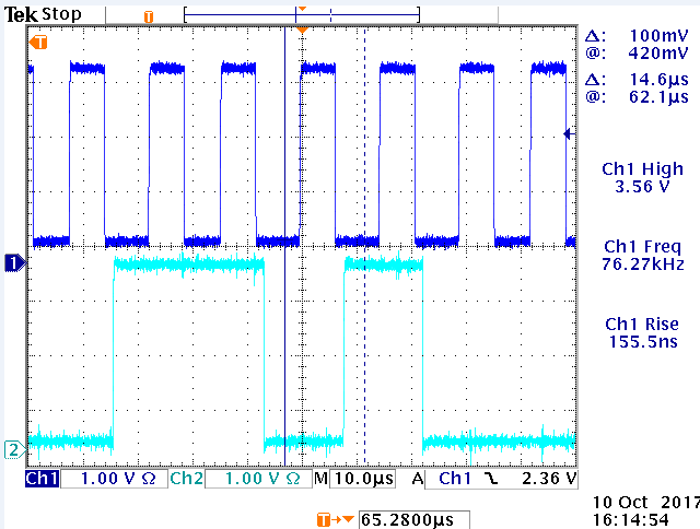
    • I2C Transaction edges look very clean:

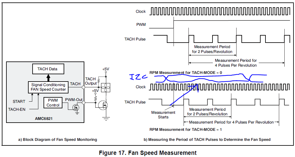
  • Per the AMC6821 datasheet we’re reading the TACH-DATA registers 0x08h (LSB), then 0x09h (MSB)


  • We are operating with a 4-wire fan.


Symptoms of the problem

  • Occasionally we see incorrect TACH readings.    For example, given a fixed fan speed, here are multiple sets of data:
    • FFFFh-0FFFh-0F92h
    • 04CCh-03CCh-03D4h
    • 04D8h-03D8h-03CCh
  • Note that the MSB changes substantially.


Observations

  • Decreasing the measurement speed from 250ms to 1s monitoring reduces the occurrence of these seemingly random errors.
  • An I2C log is attached.   Search for “***” to see where we think we’ve caught some improper reads, and how the chip is setup.
  • We’ve tried both single bye reads and dual byte reads.   Both exhibit the same phenomenon.  

TRACE.LOG

Questions

  1. We’re looking for a root-cause to these erroneous values which occur at seemingly random intervals.    Are there specific requirements regarding I2C timing that we need to follow?

Any help is much appreciated.

Don

  • Donald,

    I will look into this. Please allow me a few days.

    -Kelvin
  • Don,

    Is this a new design?  Have you got the AMC6821 to work before?

    What is your TACH-EN and TACH-MODE configuration?

    Make sure to use TACH-EN = 1, TACH-MODE = 1 for 4-wire fans.

    -Kelvin

  • Hey Kelvin,

    This is new design.  Yes, the AMC6821 works now.    With the exception of the occasional erroneous read.

    At the TACH-EN settings not included in the previously attached log file?

    Don

  • Hey there,

    Any update?

    Don

  • Don,

    Please define the symbols in the data log:
    RD, S, A, D, and ***
    I can't locate the TACH configuration in the log file.

    Please also add the scope shot of the TACH signal.

    Which control mode are you using? Software RPM control mode or other?

    Please provide the FDRC1,FDRC0 configurations.
     
    -Kelvin

  • Hi Kelvin,

    The signals in the data log are as follows:

    RD = I2C Read
    WR = I2C Write

    S = 8-bit - I2C Address = 0x34h = 00110100
    A = I2C Register Pointer
    D = I2C Data

    Decoding the first four I2C transactions in the log yields:


    WR @ 100 kHz S:34 A:01 D:80 //Reset Device via Configuration Register #2
    --> Wait here (at least to recover I2C access, and until reset is completed)
    WR @ 100 kHz S:34 A:01 D:3F //Write to Configuration Register #2
    WR @ 100 kHz S:34 A:00 D:9D //Write to Configuration Register #1
    WR @ 100 kHz S:34 A:22 D:00 //Write to DCY (Duty Cycle) Register
    --> Wait 2 sec here...
    WR @ 100 kHz S:34 A:22 D:A0 // Write to the DCY (Duty Cycle) Register)
    --> Begin a loop of 4000...
    RD @ 100 kHz S:34 A:08 D:FFFF // 2 Byte I2C Read of the TACH contents LSB first

    FDRC0/1 and Control mode can be determined from the values written into those registers..

    The erroneous measurement was captured twice in the attached log file.

    Decoding the log file that shows the erroneous transaction labelled as *** at Location #1:


    RD @ 100 kHz S:34 A:08 D:11A4 // Valid TACH Read
    RD @ 100 kHz S:34 A:08 D:11A4 // Valid TACH Read
    RD @ 100 kHz S:34 A:08 D:11A4 // Valid TACH Read
    RD @ 100 kHz S:34 A:08 D:04A4 *** // Erroneous TACH Read
    RD @ 100 kHz S:34 A:08 D:041E // Valid TACH Read
    RD @ 100 kHz S:34 A:08 D:041E // Valid TACH Read
    RD @ 100 kHz S:34 A:08 D:041E // Valid TACH Read


    Decoding the log file that shows the erroneous transaction labelled as *** at Location #2:

    RD @ 100 kHz S:34 A:08 D:041E //Valid TACH Read
    RD @ 100 kHz S:34 A:08 D:041E //Valid TACH Read
    RD @ 100 kHz S:34 A:08 D:041E //Valid TACH Read
    RD @ 100 kHz S:34 A:08 D:031E *** //Erroneous TACH Read
    RD @ 100 kHz S:34 A:08 D:03DA //Valid TACH Read
    RD @ 100 kHz S:34 A:08 D:03DA //Valid TACH Read
    RD @ 100 kHz S:34 A:08 D:03DA //Valid TACH Read

    Couple of things here:

    1. TACH reads in this case occur at speed, are continuous, and are back-to-back with little time between reads.
    2. The AMC6821 looks to be in continuous TACH update mode.
    3. The AMC6821 requires 2x TACH pulses to obtain a read per figure 17 of the datasheet.

    What happens if an I2C read occurs while the TACH is being updated? Like so:


    Don

  • Don,

    Based on your FDRC1 FDRC0 setting, you're in software DCY control mode.
    All of the glitches occur at the transition (change in fan speed). However, your log doesn't show you writing to the DCY register so why does your TACH-DATA-L changes over time (e.g. D:041E to D:03DA)?

    I would recommend adding a delay between the new DCY WR command and the TACH RD command to avoid the glitch.

    -Kelvin
  • Hi Kelvin,

    Per the previous post,


    WR @ 100 kHz S:34 A:22 D:00 //Write to DCY (Duty Cycle) Register (Set fan speed PWM to 0%)
    --> Wait 2 sec here...
    WR @ 100 kHz S:34 A:22 D:A0 // Write to the DCY (Duty Cycle) Register (Set fan speed PWM to 63%)
    --> Begin a loop of 4000...
    RD @ 100 kHz S:34 A:08 D:FFFF // 2 Byte I2C Read of the TACH contents LSB first

    Thus the fan is spinning up while we are reading the TACH register.

    Are you suggesting that we need to wait for the fan to ready steady-state before reading the TACH register? If so, how will we know when this occurs?

    Don

  • amc6821 tach.xlsx

    Don,

    Thanks for the clarification.  I understand now.  The fan is ramping up and it looks like it has four discrete windows of speeds during this time frame.  What does the PWM waveform look like from the start of the TACH read cycle?  I would assume it would be at 63% DCY already and it is the physical fan speed that is lagging behind.  It is possible that the faulty TACH readings are due to the fan changing from one speed to another and should be treated as noise:

    Are you interested in the ramp-up TACH reading or steady state? I understand that your I2C clock is 100kHz but what is the actual sampling rate of your TACH reading? Is it at 1Hz like you mention before?  At higher sampling rate you will detect high frequency events like you're seeing.

    BTW, have you trying setting the TACH-FAST bit in Configuration Register 4? When TACH-FAST = 1, the TACH data reading is updated every 250ms instead of every second.  This might help.

    Do you see faulty TACH readings once the fan has settled to 63% DCY?  What I'm getting right now is that this noise occurs just during the transitional period.

    -Kelvin

  • Thanks Kelvin,

    You're getting closer. Couple of things:

    - We are in software DCY control mode. Thus we are writing a specific value to the DCY register. Shouldn't the output PWM (driving the fan) go from 0% -> 63% instantaneously? More so, it should stay at that value indefinitely (barring a change to the DCY register).

    - We see these erroneous measurements at both 250ms sampling rate and 1s sampling rate. However, less of them occur at 1s sampling rate.

    - I don't have scope shots for the TACH/PWM outputs, but I'll get those for you. Should we be looking for something specific?

    - I believe that the erroneous measurements go away once the fan has settled to steady state. I'll double-check to confirm.

    Don
  • Hi Kelvin,

    FYI, we've confirmed the same behaviour using the AMC6821 EVM.    Have you managed to dig up more information from the designer?

    Don

  • I will copy you in the email. We haven't heard back from the designer.

    -Kelvin
  • Don,

    Our designer suspects the occasional glitches are due to a design issue.  The issue is related to the clock domain crossing of the parallel Tach value bus. This bus is for the synchronization between the internal oscillator clock and the I2C SCL. This issue may happen at the time when the low byte is requested.

    You may consider the follow workarounds:

    1. The first possible workaround, if acceptable, is to do double I2C readings and check for settled Tach value.
    2. The second workaround, if acceptable, is to read only after a new PWM value is settled. 

    -Kelvin