This thread has been locked.

If you have a related question, please click the "Ask a related question" button in the top right corner. The newly created question will be automatically linked to this question.

TDC1000-TDC7200EVM: Some problems with board design and COMP-IN signal

Part Number: TDC1000-TDC7200EVM

Hi, team

I bought a TDC1000-TDC7200EVM last week and it showed a great performance in zero flow test.

I also designed a TDC based board months ago, which uses a TDC-GP21 as stop watch and TDC1000 as AFE. But test result is even worse than our early design with separate anlog circuits, as my workmate described in .

My design with TDC1000 is showed in the attach. Main difference with EVM is the stop watch, while TDC-GP21 also has a resolution up to 50ps.  So I don't think this will cause that large error.  I have concluded some probable problems as following:

1. TDC-GP21 has a external 4MHz osillator while TDC1000 uses a 4MHz clock from MCU;

2. TDC1000 was supplyed by two 3% linear regulators(3V and 5V);

3. Perhaps PCB layout problem?

Problem 1 I have conducted various tests, but still found nothing. I wonder if you can find any vital problem through the design or have any recommended solutions.

TDC based design.pdf

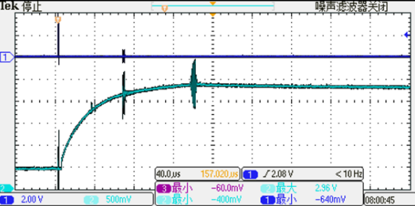
I also have some problems with the signal. I found that the COMP-IN signal in my own design showed a fall down trend in a measurement cycle, as shown in the figure:

Problem 2 Why does VCOM (or COMP-IN) falls down before the end of the test? BTW, why I can't even see the charging process when using the EVM?

Another problem is that, when I connect UART pins of my board to a TTL-to-RS232 converter(especially the supply pin), the noise on COMP-IN signal will be much larger than before, as shown in the figure:

Problem 3 I have found that the noise comes from VCOM pin, but I cant understand why. Could you please explain that?

Best wishes!

  • Hi Chengwei,

    Please allow a few days for me to review the design. I will get back to you by the end of the week.

    Regards,
  • Hi Scott, thank you for replying.

    Another problem occured today when testing, still in zero flow.

    Figure 1 is the raw data in last week's test(date: 3.06) and Figure 2 is that in today's(date:3.13). As you can see, there must be something wrong.

    Figure 1 Raw data in last week's


    Figure 2 Raw data in today's


    In case of broken of sensor, I also conducted a test with my own board, figure 3 shows the result.(Worse than figure 1, but better than figure2)

    Figure 3 Today's test result with my own board


    So the sensor still works properly, as to say, the problem must lie in theEVM. But I did nothing to the board during this week, so it really confuses me. BTW, I found that VCOM seems unstable during measurement cycles, but I'm not sure if this is a normal phenomenon and can't find the reason. Have you ever come with this problem?

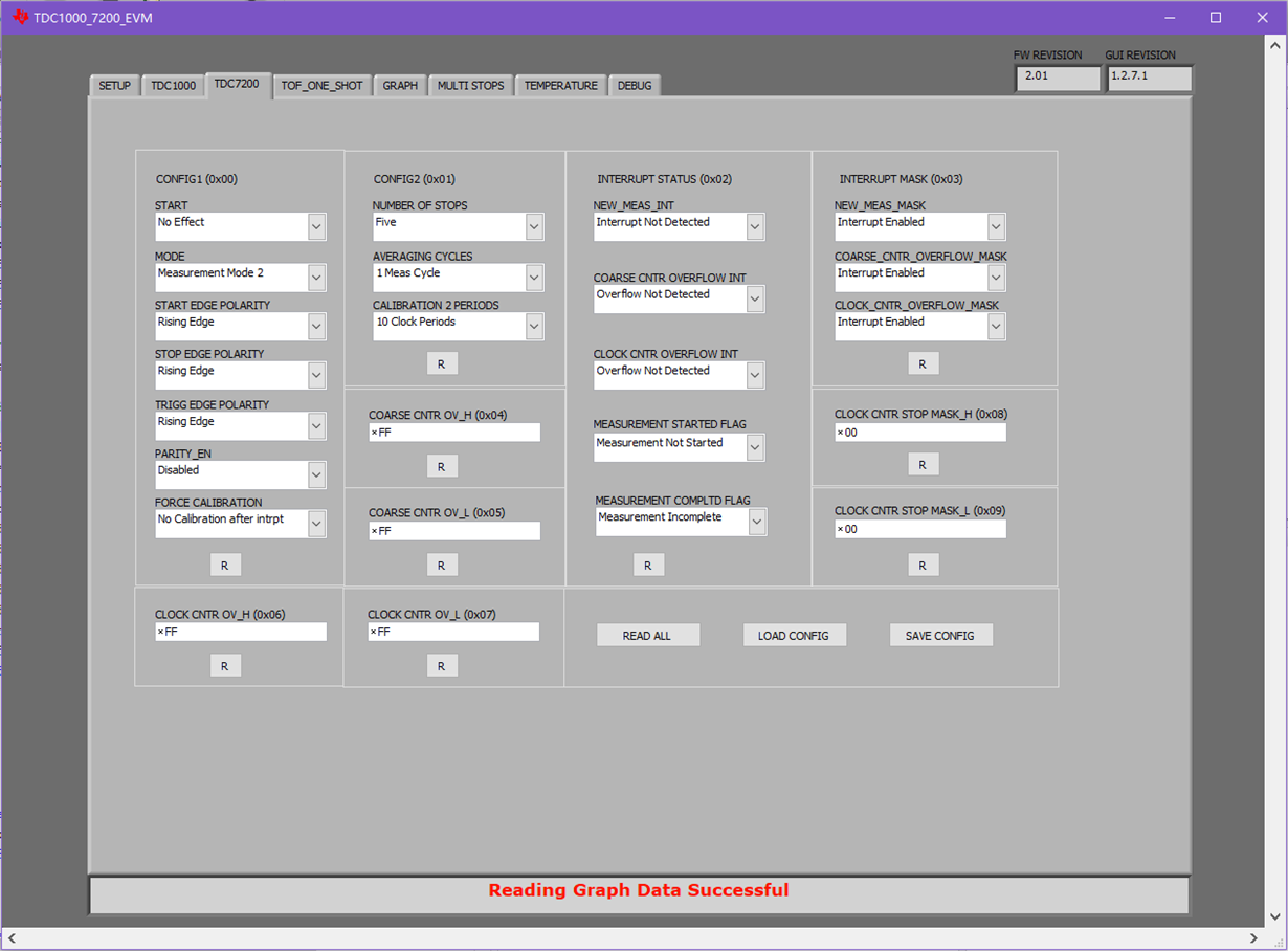
    PS. Version of the program running in the EVM is v2.01-1MHz, single TOF of my sensor is about 70 microseconds, and Figure 4~6 is configuration settings in the UI software.

    Thank you for your patience.

    Best wishes!

  • Thanks for the update Chengwei. I will need some more time to review, so I will get back to you by 3/21.

    Thanks,
  • Hi Chengwei,

    The design looks alright to me. I'm curious why you are using the an external clock for the GP21, but the MSP clock for the TDC1000. I would recommend using the same clock for both (not because they need to be synced, but just because the external clock is likely to have better performance than the MSP430 clock output at that frequency).

    I will have to look further into the noise issue.

    Regards,
  • Hi Scott, thank you for your reply, I'm now redesigning my circuit.

    In my last reply, I told you that zero testing result of the EVM goes worse without any reason. I thought problem must happen on the board, but last weekend I found it blames on my desktop PC, as I got a fine result when using my notebook for testing...although I didn't find a exact reason.

    As the noise issue still exsists, I don't know how to design a serial comm interface for UART. So I really wanna know where the noise from, and it would be great if you could send me a reference design.

    Thanks