
- Ask a related questionWhat is a related question?A related question is a question created from another question. When the related question is created, it will be automatically linked to the original question.
My question relates to topology of laser diode drivers, not LED drivers, but didn’t know where else to post it. I am trying to design a laser diode driver for TOF application and was thinking about using the capacitive discharge to generate a very short and fast rise current pulse. I also thought about the inductive discharge topology.
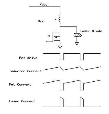
Then I read the SBAA209A app note and I thought the “shunt switching” circuit mentioned there is similar to the inductive discharge circuit I pictured above. However after watching this video by Larry Li: https://training.ti.com/3d-time-flight-illumination-subsystem-design-and-component-selection?cu=1127769 I started to have doubts this is the case. In the video the duty cycle is said to be 50%.

I am not sure what current waveforms to expect from the “shunt switching” circuit. Is there an app note describing this? I tried searching the TI website, but no luck. I would highly appreciate any feedback.
Thank you,
Michael


