This thread has been locked.

If you have a related question, please click the "Ask a related question" button in the top right corner. The newly created question will be automatically linked to this question.

RTOS/AWR1642BOOST: Where is the HPF ?

Part Number: AWR1642BOOST

Tool/software: TI-RTOS

Bottom Line Up Front: Does the HPF1 from the mmWave SDK modify the first filter's high-pass corner frequency in the receiver subsystem image and does the HPF2 from the mmWave SDK modify the second filter's low-pass corner frequency in the receiver subsystem image?

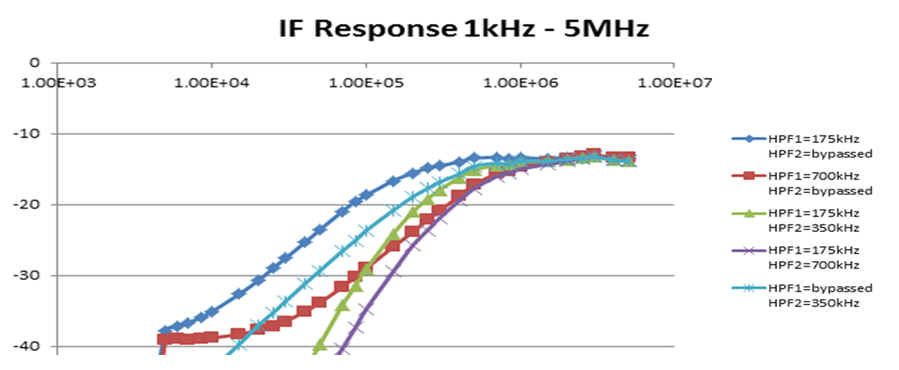
This is a similar question to the one username "ZHENGGUO SUN" posted awhile ago. I acknowledge that the SDK specifies you can define two High-pass filter corner frequencies as shown in the image below:

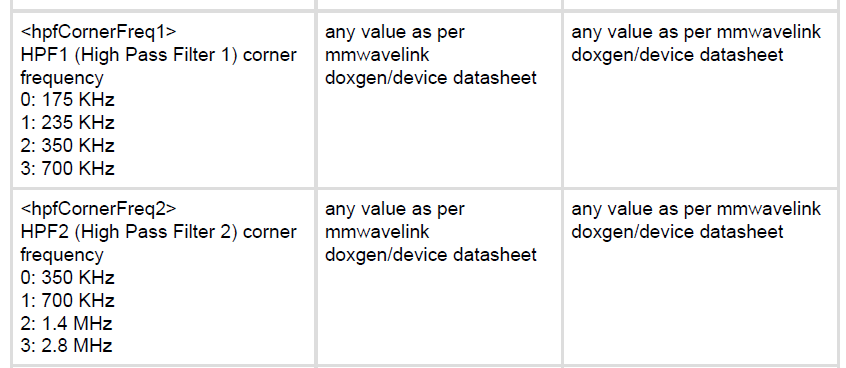
But I don't understand why there are two HIGH pass filters. It would make more sense if the first filter was a high pass filter and the second was a low pass filter (therefore creating a bandpass of interest in the IF bandwidth that is always 3.125MHz or less in the complex signal sampling case) Please refer to the below image of the hardware block diagram of the receiver system to see what I am talking about:

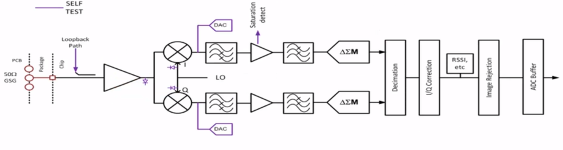
Following both the real and complex mixers is a 3 block chain: high pass filter, amplifier, low pass filter. It would make sense if the SDK is referring to these two filters, correct? i.e. the goal is to filter out low frequency noise and the high frequency noise that the ADC will not be able to accurately sample due to the Nyquist criterion

  • The architecture has two High Pass Filters.  The are is series,  They are shown after the quadrature down conversion mixer.  

    The combination of the two HPF1, HPF2 provide the bumper reflection, radome reflection attenuation.  The 175khz, 350khz value is shown in the attached filter plot.

    A typical lower limit frequency is 200khz with 20db attenuation.  After the HPF is a 2nd gain stage, and then the traditional Low Pass filter before the ADC.

    There is no low frequency filter selection.  The ADC samples at 900 or 1800Msps.  The High Pass filter is operating in the DC-300khz range.  

    The first gain stage before the quadrature mixer, and the second gain stage combine to provide the 24-48db LNA gain.

    Note: the filter curves that show a Bypass condition are not settable in the mmwave SDK functions.

    Regards,

    Joe QUintal

  • But the low pass filter before the ADC cannot be modified by the user, correct? It just filters the signal to the appropriate ADC bandwidth?
  • Yes the low pass filter provides Nyquist zone 1 filtering for the ADC input. There is no user adjustment.

    The signal of interest is .2Mhz to 17.5Mhz, the ADC is sampling at 900 or 1800Mhz.
    The ADC sample rate selection is part of the LowPower mmwave function. The Digital Front End has filtering, decimation, resampling, and frequency translation to provide the 2 - 17.5Mhz Complex 1x, 4 - 37.5Mhz Real, -2 to 2Mhz to -8.75 / 8.75Mhz Complex 2x DFE output.

    Regards,
    Joe QUintal