This thread has been locked.

If you have a related question, please click the "Ask a related question" button in the top right corner. The newly created question will be automatically linked to this question.

AWR1243: TestPattern Validation in Xilinx FPGA

Part Number: AWR1243

Hi All,

I'm Validating my LVDS Logic Implemented in Xilinx FPGA

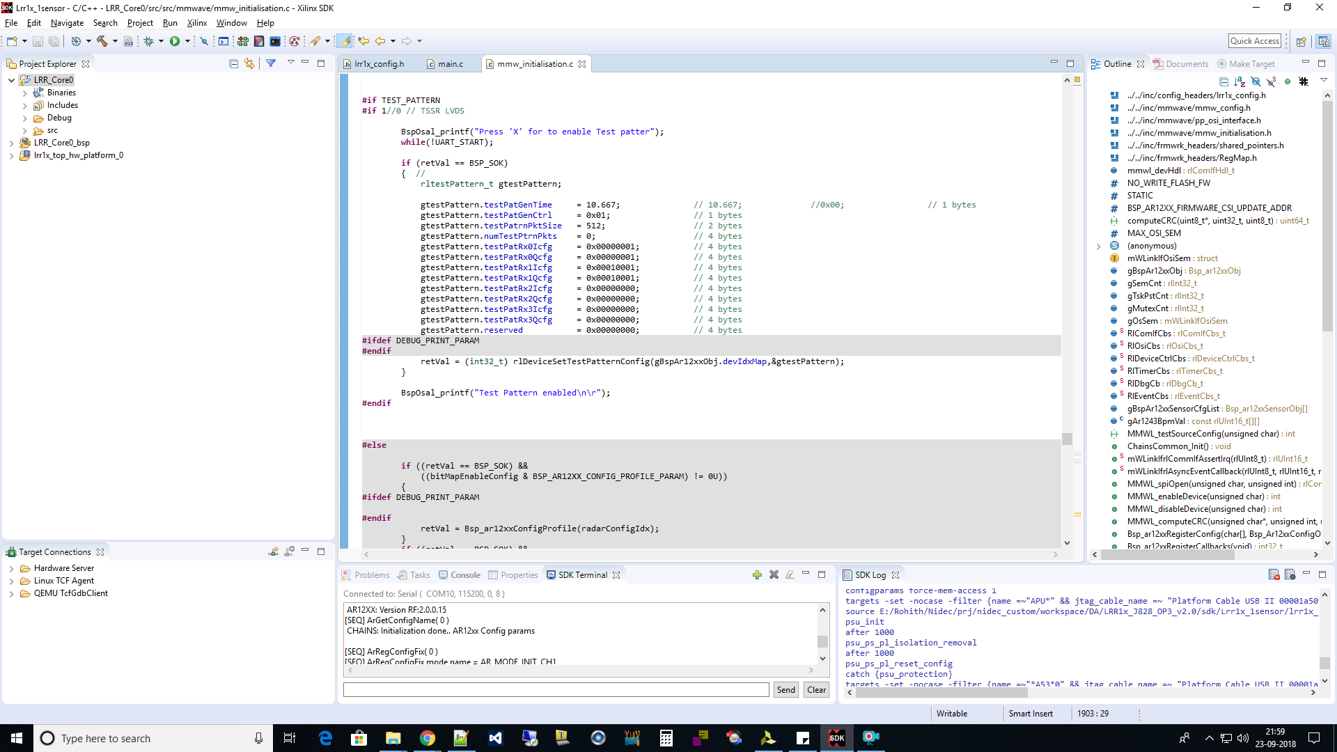
LVDS Data rate = 900 Mbps & My test pattern related setting in mmWave SDK are attached in the below screenshot 

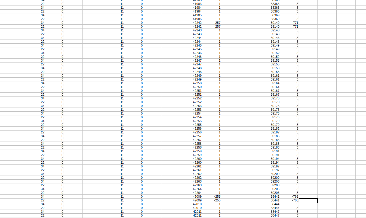
In my Chipscope capture of LVDS data (after serial to parallel conversion), seeing a jump the counter data. at the same time, I'm seeing "LVDS_Valid" signal going low.

The Jump of the counter is dependent on test pattern packet size (tested for 512 or 256)

This can be observed in figure "LVDS_Vivado_Capture1.png" and LVDS_Vivado_Capture_Analysis.xlsx" (data captured multiple times)

My Question is 

1. Is this Behaviour expected? If not what could be the reasons.

2. Can this be a C-buff Overflow? 

3. Do you think any Issue at FPGA? (i'm capturing data signals directly, no buffering)

LVDS_Vivado_Capture_Analysis.xlsx

Thanks In Advance

Rohith

  • Hi,

    We have to check with our LVDS expert. WIll get back to you as soon as possible

    thank you
    cesar
  • Hello ,
    The DATA VALID would be high during the period the chirp data is being sent out and will go low until the next chirp data starts. The test pattern is also emulated as 'chirps' , just that the data is fixed rather than actual ADC measurements. So yes, data valid will go low.

    Regards,
    Vivek
  • Hi Vivek,

    Thank you for  the comment. I believe that my Colleague didn't put up the question properly.

    We understand that the DATA_VALID will be low between packets.

    Out problem/issue is, there is a large deviation in the difference between the last sample of current packet and the fist sample of next packet. Our observation are:

    1) This deviation happens at the start of every packet, all the time.

    2) The difference is usually 511, 512 or 513, when the packet size is 512. The difference is around 255 when the packet size is 256.

    3) We have estimated that this change happens at start of every new packet by looking at Data_VALID going low.

    4)Within a packet, the samples increment by 1, as expected.

    5) Across packet also we expect the samples to be incremented by 1 only (not happening). We are not sure, whether this expectation is correct.

    Any help on this part would be highly appreciated.

    Thanks in Advance,

    Santhana Raj

  • Hello Santhana,
    OK, now I understand the issue. The value is expected to the continuous across samples.
    If the samples are been generated faster than what the LVDS interface can send out then some of the samples could be missed. Can you increase the value for "TestPattern_Gen_timing" value so that the rate of samples slows down?

    Regards,
    Vivek
  • Hi Vivek,

    Thank s for the idea.
    As you can see in the image earlier, currently the Gen_timing value if 10.667 to generate data at 18.75 MSPS in complex.

    We went ahead and tested with Gen_Timing of 10 and 15, but we observed the same issue here also.
    The error phenomenon was same

    I am not sure why I have to increase the Gen_timing value. The value of 10.667 should result in (200/10.667) = 18.75MSPS.
    In bit rate it should be 600Mbps (18.75M*16*2).
    The LVDS data line configuration is set to 900Mbps.
    So I expect that since the data is generated at 600Mbps and the LVDS is sending out at 900Mbps, there should not be any overflow in the buffers. Can you confirm me whether my expectation is correct??


    Thanks for any help on this issue.
    Santhana Raj
  • Hello Santhana,
    Your expectation seems correct.
    In that case the FPGA seems to be missing some samples for some reason?

    Regards,
    Vivek
  • Hi Vivek,

    We are not sure about this, because, the data is received properly within a packet. The mismatch is present only at the start of the new packet.

    Can you suggest any way to verify/ debug this problem??
  • Hi 
    Please find the image where we show the real and image data captured in excel sheet.
    Packet size (256), real and Imaginary values are the same.
    As you can see, there is a jump of 257 / 771 on packet start and exactly after 24 samples (depends on packet size), there is jump down/decrease in value of exactly 255 /  765.
    This makes the value match and gets back us to the values as expected from test Pattern.
    My question is,
    Is this expected??? Can anyone help us on why this is happening???
    Please note that the first two channels have constant Test Pattern and there is no jump with this case
  • Hello Rohith,
    Can you increase the Gen timing value of 128 or something higher to reduce the rate at which the samples are generated?

    Regards,
    Vivek
  • Hi Vivek,

    We have reduced the sample generation time to 8,4,2,1 and finally to 0.5Mbps. (by increasing the Gen timing value as you suggested)

    We see that the jump that we were seeing in 18.5Mbps has reduced.

    At 1 Mbps and 0.5 Mbps, we see that the first sample of all the 4 lanes in a packet are wrong. They are basically the first 4 values of next packet as seen in the data capture below.

    Any help on this issue would be highly appreciated.

    One more question,

    Reducing data generation speed, reduces the wrong values in captured data. Does this mean that the TI's test generator has issues at very low Gen_timing value???

  • Hello Shanthana,
    Thanks for the confirmation, so does that mean with lower speeds you are no seeing any jumps now between the samples?
    This interface is only intended for basic checks on the data interface , not intended to be run at the full sampling rate.

    The start packet could be arbitory in the ramp based on where the internal counter was last and the roll back after 65535 is expected since its 16bit width.

    Regards,
    Vivek
  • Thanks a lot, Vivek for your kind explanation about the issue. Now we understand and shall follow as per your suggestions

    Currently, we also got ADC data. but in In Initial few chirps the first sample is zero. Can you please point us, what could be the Issue ???

    I also have one more question about test pattern

    For Slave sensors, do I need to configure the master first to get the test pattern???

  • Hello Rohith,

    For the ADC data are you using the DCA1000 to capture the data?

    Regarding the slave sensors, yes you need to configure the master first so that it provides the 40Mhz clock to the slave. Only then can you configure the slave devices.

    Regards,

    Vivek

  • Hi Vivek,

    For ADC / TestPattern we are NOT using DAC1000.
    We have a custom setup to Configure and Capture Sensor data from Xilinx Zynq SoC

    In Continuation to earlier post,
    >>> Currently, we also got ADC data. but in In Initial few chirps the first sample is zero. Can you please point us, what could be the Issue ???
    We have added Chirp Profile Information to ADC data. with this we have not seen any ZEROs at the start of the chirp.
    The Issue appers only when you disable chirp profile Info.

    Can you please give us a pointer to resolve this issue

    Thanks for your support
  • Hello Rohith,
    This is not expected, we have not seen complete zero data on the ADC data. I suspect it might have to do something on the capture side.
    How many samples of zeros do you get?

    Regards,
    Vivek

  • Hi Vivek,

    Only 1st sample of few chiprs (2nd chirp to 6th chirp). all other chirps has non-zero first sample
    Please let us know, If you would like know more information

    Thanks for your time and support
  • Hi Vivek,

    We have figured out the issue in our DDR storage data path.

    Now, we have got the ADC data which seems to be correct.

    Thanks your time and support