Other Parts Discussed in Thread: IWR1642
Hi,
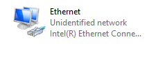
I have issues with configuring the board to connected through Ethernet. I followed the necessary steps.
Configured IP to static. 192.168.33.30
SOP0,SOP1
DCA1000 switches configured
SW1:
16BIT_ON and the other two are off
SW2
6.7.8 --> SW1,2,3
5: SW_CONFI
4: RAW_DATA
3: 1243_MODe
2: ETH
1:LVDS
GM: Constructor
GM: Tue Dec 18 11:36:54 2018
RSTD.Transmit("/Settings")
[11:36:55]
[11:36:55] ### Running Startup script: "C:\ti\mmwave_studio_02_00_00_02\mmWaveStudio\Scripts\Startup.lua" ###
[11:36:55] RSTD.SetAndTransmit ("/Settings/Scripter/Display DateTime" , "1")
[11:36:55] RSTD.SetAndTransmit ("/Settings/Scripter/DateTime Format" , "HH:mm:ss")
[11:36:55] Scripter ignored: Attempt to UnBuild() again or before Build.
[11:36:55] RSTD.SetVar ("/Settings/Clients/Client 0/Dll" , "C:\\ti\\mmwave_studio_02_00_00_02\\mmWaveStudio\\Clients\\\\LabClient.dll")
[11:36:55] RSTD.SetVar ("/Settings/Clients/Client 0/Use" , "TRUE")
[11:36:55] RSTD.SetVar ("/Settings/Clients/Client 1/Use" , "FALSE")
[11:36:55] RSTD.SetVar ("/Settings/Clients/Client 2/Use" , "FALSE")
[11:36:55] RSTD.SetVar ("/Settings/Clients/Client 3/Use" , "FALSE")
[11:36:55] RSTD.SetVar ("/Settings/Clients/Client 4/Use" , "FALSE")
[11:36:55] RSTD.SetVar ("/Settings/AL Client/AL Dll" , "C:\\ti\\mmwave_studio_02_00_00_02\\mmWaveStudio\\RunTime\\SAL.dll")
[11:36:55] RSTD.SetVar ("/Settings/Clients/Client 0/GuiDll" , "")
[11:36:55] RSTD.SetVar ("/Settings/AutoUpdate/Enabled" , "TRUE")
[11:36:55] RSTD.SetVar ("/Settings/AutoUpdate/Interval" , "1")
[11:36:55] RSTD.SetVar ("/Settings/Monitors/UpdateDisplay" , "TRUE")
[11:36:55] RSTD.SetVar ("/Settings/Monitors/OneClickStart" , "TRUE")
[11:36:55] RSTD.SetVar ("/Settings/Automation/Automation Mode" , "false")
[11:36:55] RSTD.Transmit("/")
[11:36:55] RSTD.SaveSettings(): Settings saved to "C:\Users\abe_mhamdan\AppData\Roaming\RSTD\config.xml"
[11:36:56] RSTD.Build()
[11:36:56] RSTD.SaveSettings(): Settings saved to "C:\Users\abe_mhamdan\AppData\Roaming\RSTD\config.xml"
[11:36:56] RSTD.Transmit("/")
[11:36:56] RSTD.AL_Build()
[11:36:56] RSTD.AL_LoadXml()
[11:36:56] RSTD.Transmit("/")
[11:36:56] RSTD.AL_Init()
[11:36:56] RSTD.Clients_Build()
[11:36:56] GM: Init
[11:36:56] GM: Loaded 'C:\ti\mmwave_studio_02_00_00_02\mmWaveStudio\Clients\\LabClient.dll'
[11:36:56] GM: 1 Guest (s) init
[11:36:56] GM: 1 Module(s) init
[11:36:56] GM: 2 Tab (s) init
[11:36:56] RSTD.Client_LoadXml()
[11:36:56] [RadarAPI]: Starting Matlab Engine..
[11:37:15] [RadarAPI]: Matlab Engine Started!
[11:37:18] [RadarAPI]: ar1.LoadSettings('C:\Users\abe_mhamdan\AppData\Roaming\RSTD\ar1gui.ini')
[11:37:18] TESTING = false
[11:37:18]
[11:37:18] ***Script completed successfully.***
[11:37:25] [RadarAPI]: Opening Gpio Control Port()
[11:37:25] [RadarAPI]: Status: Passed
[11:37:25] [RadarAPI]: Opening Board Control Port()
[11:37:25] [RadarAPI]: Status: Passed
[11:37:26] [RadarAPI]: ar1.FullReset()
[11:37:26] [RadarAPI]: Status: Passed
[11:37:27] [RadarAPI]: Closing Board Control Port()
[11:37:27] [RadarAPI]: Status: Passed
[11:37:27] [RadarAPI]: Closing Gpio Control Port()
[11:37:27] [RadarAPI]: Status: Passed
[11:37:27] [RadarAPI]: ar1.SOPControl(2)
[11:37:27] [RadarAPI]: Status: Passed
[11:37:28] [RadarAPI]: ar1.Connect(5,115200,1000)
[11:37:29] [RadarAPI]: ar1.Calling_IsConnected()
[11:37:31] [RadarAPI]: ar1.SelectChipVersion("AR1642")
[11:37:31] [RadarAPI]: Status: Passed
[11:37:31] [RadarAPI]: RS232 is not connected ..!!!!
[11:37:31] [RadarAPI]: ar1.frequencyBandSelection("77G")
[11:37:31] [RadarAPI]: ar1.SelectChipVersion("XWR1642")
[11:37:31] [RadarAPI]: Status: Passed
[11:37:31] Device Status : XWR1642/QM/SOP:2/ES:2
[11:37:32] [RadarAPI]: ar1.SelectChipVersion("AR1642")
[11:37:32] [RadarAPI]: Status: Passed
[11:37:32] [RadarAPI]: ar1.SelectChipVersion("XWR1642")
[11:37:32] [RadarAPI]: Status: Passed
[11:37:32] Device Status : XWR1642/QM/SOP:2/ES:2
[11:37:32] [RadarAPI]: ar1.SaveSettings('C:\Users\abe_mhamdan\AppData\Roaming\RSTD\ar1gui.ini')
[11:39:01] [RadarAPI]: ar1.ReadRegister(0xffffe214, 0, 31)
[11:39:01] [RadarAPI]: ar1.ReadRegister(0xffffe210, 0, 31)
[11:39:01] [RadarAPI]: ar1.ReadRegister(0xffffe218, 0, 31)
[11:39:01] [RadarAPI]: ar1.DownloadBSSFw("C:\\ti\\mmwave_studio_02_00_00_02\\mmWaveStudio\\Scripts\\..\\..\\rf_eval_firmware\\radarss\\xwr16xx_radarss.bin")
[11:39:02] [RadarAPI]: Downloading BSS Patch RPRC Binary..
[11:39:09] [RadarAPI]: ar1.GetBSSFwVersion()
[11:39:09] [RadarAPI]: BSSFwVersion:(02.00.00.01 (05/10/17))
[11:39:10] [RadarAPI]: ar1.GetBSSPatchFwVersion()
[11:39:10] [RadarAPI]: BSSPatchFwVersion:(01.02.00.03 (24/10/18))
[11:39:10] BSS FW Download Success
[11:39:12] [RadarAPI]: ar1.DownloadMSSFw("C:\\ti\\mmwave_studio_02_00_00_02\\mmWaveStudio\\Scripts\\..\\..\\rf_eval_firmware\\masterss\\xwr16xx_masterss.bin")
[11:39:12] [RadarAPI]: Downloading MSS RPRC Binary..
[11:39:23] MSS FW Download Success
[11:39:25] [RadarAPI]: ar1.PowerOn(0, 1000, 0, 0)
[11:39:25] [RadarAPI]: Status: Passed
[11:39:25] MSS power up done async event received!
[11:39:25] Power On Success
[11:39:26] [RadarAPI]: ar1.RfEnable()
[11:39:26] [RadarAPI]: Status: Passed
[11:39:26] BSS power up done async event received!
[11:39:27] [RadarAPI]: ar1.GetBSSFwVersion()
[11:39:27] [RadarAPI]: BSSFwVersion:(02.00.00.01 (05/10/17))
[11:39:28] [RadarAPI]: ar1.GetBSSPatchFwVersion()
[11:39:28] [RadarAPI]: BSSPatchFwVersion:(01.02.00.03 (24/10/18))
[11:39:28] RF Enable Success
[11:39:29] [RadarAPI]: ar1.ChanNAdcConfig(1, 1, 0, 1, 1, 1, 1, 2, 1, 0)
[11:39:29] [RadarAPI]: Status: Passed
[11:39:29] ChanNAdcConfig Success
[11:39:30] [RadarAPI]: ar1.LPModConfig(0, 1)
[11:39:30] [RadarAPI]: Status: Passed
[11:39:30] LPModConfig Success
[11:39:32] [RadarAPI]: ar1.RfInit()
[11:39:32] RF Init async event received!
[11:39:32] [RadarAPI]: Time stamp, Temperture: 5843,41; APLL Status, Update: 1, 0; SynthVCO1 Status, Update: 1, 1; SynthVCO2 Status, Update: 1, 1; LODist Status, Update: 1, 1; RxADCDC Status, Update: 1, 1; HPFcutoff Status, Update: 1, 1; LPFcutoff Status, Update: 1, 1; PeakDetector Status, Update: 1, 1; TxPower Status, Update: 1, 1; RxGain Status, Update: 1, 1; TxPhase Status, Update: 0, 0; RxIQMM Status, Update: 1, 1;
[11:39:32] [RadarAPI]: Status: Passed
[11:39:32] RfInit Success
[11:39:33] [RadarAPI]: ar1.DataPathConfig(1, 1, 0)
[11:39:33] [RadarAPI]: Status: Passed
[11:39:33] DataPathConfig Success
[11:39:34] [RadarAPI]: ar1.LvdsClkConfig(1, 1)
[11:39:34] [RadarAPI]: Status: Passed
[11:39:34] LvdsClkConfig Success
[11:39:35] [RadarAPI]: ar1.LVDSLaneConfig(0, 1, 1, 0, 0, 1, 0, 0)
[11:39:36] [RadarAPI]: Status: Passed
[11:39:36] LVDSLaneConfig Success
[11:39:37] [RadarAPI]: ar1.ProfileConfig(0, 77, 100, 6, 60, 0, 0, 0, 0, 0, 0, 29.982, 0, 256, 5000, 0, 0, 30)
[11:39:37] [RadarAPI]: Status: Passed
[11:39:37] ProfileConfig Success
[11:39:38] [RadarAPI]: ar1.ChirpConfig(0, 0, 0, 0, 0, 0, 0, 1, 1, 0)
[11:39:38] [RadarAPI]: Status: Passed
[11:39:38] ChirpConfig Success
[11:39:39] Test Source Already Disabled...!!!
[11:39:39] [RadarAPI]: Status: Passed
[11:39:39] [RadarAPI]: ar1.FrameConfig(0, 0, 8, 128, 40, 0, 1)
[11:39:39] [RadarAPI]: Status: Passed
[11:39:39] FrameConfig Success
[11:39:40] [RadarAPI]: ar1.SelectCaptureDevice("DCA1000")
[11:39:40] [RadarAPI]: passed
[11:39:40] SelectCaptureDevice Success
[11:39:41] [RadarAPI]: StatusDCCard Event Registered
[11:39:41] [RadarAPI]: Status: Passed
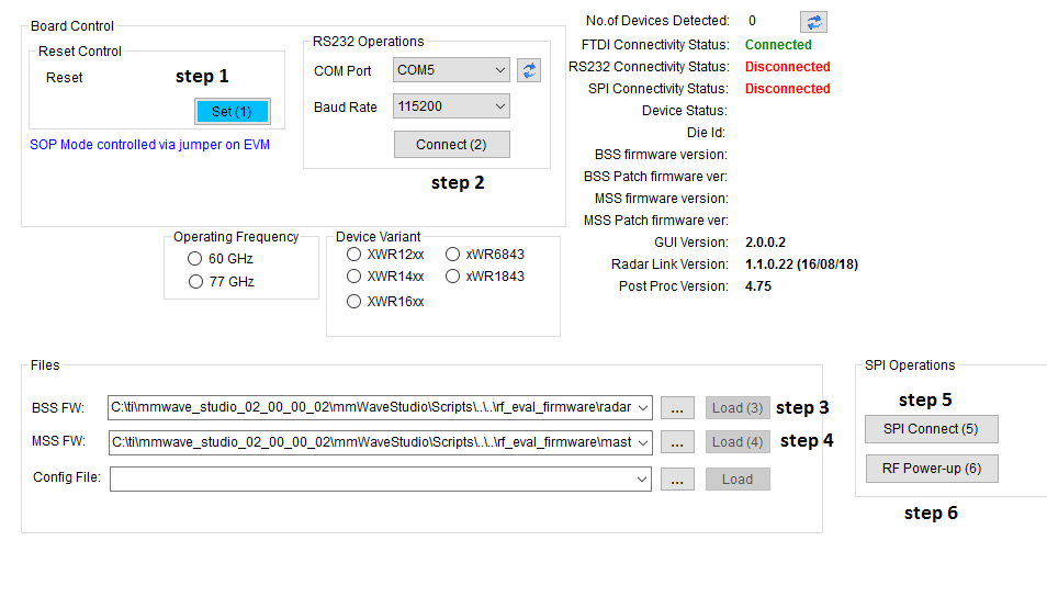
[11:39:41] [RadarAPI]: ar1.CaptureCardConfig_EthInit("192.168.33.30", "192.168.33.180", "12:34:56:78:90:12", 4096, 4098)
[11:39:41] [RadarAPI]: Status: Passed
[11:39:43] Ethernet Cable is disconnected Please check.....!!!
[11:39:43] CaptureCardConfig_EthInit Success
[11:39:44] [RadarAPI]: ar1.ConfigureRFDCCardMode(1, 2, 1, 2, 3, 30)
[11:39:44] [RadarAPI]: Status: Passed
[11:39:44] CaptureCardConfig_Mode Success
[11:39:45] [RadarAPI]: ar1.CaptureCardConfig_PacketDelay(25)
[11:39:45] [RadarAPI]: Status: Passed
[11:39:45] CaptureCardConfig_PacketDelay Success
[11:39:46] [RadarAPI]: ar1.CaptureCardConfig_StartRecord("C:\\ti\\mmwave_studio_02_00_00_02\\mmWaveStudio\\Scripts\\..\\PostProc\\adc_data.bin", 1)
[11:39:46] [RadarAPI]: Status: Passed
[11:39:47] [RadarAPI]: ar1.StartFrame()
[11:39:47] [RadarAPI]: Status: Passed
[11:39:47] Frame start async event received!
[11:39:48] Frame End async event received!
[11:39:48] [RadarAPI]: Frame Ended
[11:39:49] Please wait for a few seconds for Packet reorder utility processing .....!!!!
[11:39:49] [RadarAPI]: Packet Reorder Utility Started...please wait...
[11:39:49] [RadarAPI]: ar1.PacketReorderZeroFill("C:\\ti\\mmwave_studio_02_00_00_02\\mmWaveStudio\\Scripts\\..\\PostProc\\adc_data_Raw_0.bin", "C:\\ti\\mmwave_studio_02_00_00_02\\mmWaveStudio\\Scripts\\..\\PostProc\\adc_data.bin", "C:\\ti\\mmwave_studio_02_00_00_02\\mmWaveStudio\\Scripts\\..\\PostProc\\pktlogfile.txt")
[11:39:54] [RadarAPI]: Packet Reorder Utility process completed!
[11:40:04] Packet reorder utility processing done.....!!!!
[11:40:04] Please wait for a few seconds for matlab post processing .....!!!!
[11:40:04] [RadarAPI]: ar1.StartMatlabPostProc("C:\\ti\\mmwave_studio_02_00_00_02\\mmWaveStudio\\Scripts\\..\\PostProc\\adc_data.bin")
[11:40:05] [RadarAPI]: Error:
[11:40:05]
[11:40:05] ... MWMCR::EvaluateFunction error ...
[11:40:05] 18-Dec-2018 11:40:05: The file C:\ti\mmwave_studio_02_00_00_02\mmWaveStudio\Scripts\..\PostProc\adc_data.bin is empty. Please capture more data.,1,
[11:40:05] Error in => process_adc_data.m at line 52.
[11:40:05]
[11:40:05] ... Matlab M-code Stack Trace ...
[11:40:05] at
[11:40:05] file C:\Users\ABE_MH~1\AppData\Local\Temp\abe_mhamdan\mcrCache8.5.1\Matlab0\Logging\log_status.m, name log_status, line 32.
[11:40:05] at
[11:40:05] file C:\Users\ABE_MH~1\AppData\Local\Temp\abe_mhamdan\mcrCache8.5.1\Matlab0\Processing_functions\read_adc_data.m, name read_adc_data, line 28.
[11:40:05] at
[11:40:05] file C:\Users\ABE_MH~1\AppData\Local\Temp\abe_mhamdan\mcrCache8.5.1\Matlab0\MatlabPostPr\process_adc_data.m, name process_adc_data, line 52.
[11:40:05]
[11:40:05]
[11:40:05] Trace:
[11:40:05] at MathWorks.MATLAB.NET.Utility.MWMCR.EvaluateFunction(String functionName, Int32 numArgsOut, Int32 numArgsIn, MWArray[] argsIn)
[11:40:05] at MathWorks.MATLAB.NET.Utility.MWMCR.EvaluateFunction(Int32 numArgsOut, String functionName, MWArray[] argsIn)
[11:40:05] at MatlabPostProcGui.MatlabPostProcGUIClass.process_adc_data(MWArray adc_file_name, MWArray force_cont_stream_mode)
[11:40:05] at AR1xController.frmAR1Main.iStartMtlabPostProc()
[11:40:14]
[11:40:14] ***Script completed successfully.***