This thread has been locked.

If you have a related question, please click the "Ask a related question" button in the top right corner. The newly created question will be automatically linked to this question.

AWR1642BOOST: & DCA1000 Raw Data Units

Part Number: AWR1642BOOST
Other Parts Discussed in Thread: AWR1642

Hello TI,

I have a few questions related to the data collected with an AWR1642 and handled through a DCA1000. Using these forums before making a post I have solved almost all of my own issues but I have one point I am still confused on. Let me walk you through what I know to try and make clear what it is I'm stuck on so I don't get directed to things I have already seen or waste your time.

I started by configuring my radar and LVDS capture to be compatible with the information found in the "Mmwave Radar Device ADC Raw Data Capture" Application Note, "mmWave Studio GUI", "Programming Chirp Parameters in TI radar Devices", and " DCA1000 Data Capture Card" pdfs. With everything set here I am able to capture moving target data that I can see in the mmWave Post Processing GUI and successfully create .bin files. I found the code to convert the .bin file into a MATLAB object and added my own post processing code to create a radar data cube for analysis.

The part I am stuck on is units. When I read in the ADC data, the code provided in "Mmwave Radar Device ADC Raw Data Capture" reads it in as 'int16'. My understanding is at this level the data is in "ADC count" units and will range from +/- (2^(numBits-1))/2 i.e +/- 16,384, since I am using 16-bit values. A portion  of a frame that has 128 chirps to form a Doppler axis and 512 ADC samples per chirp return to form a range axis is shown below. The values recorded by the ADC are much smaller than the ADC limits, but they are all still within the theoretical limits which is encouraging.

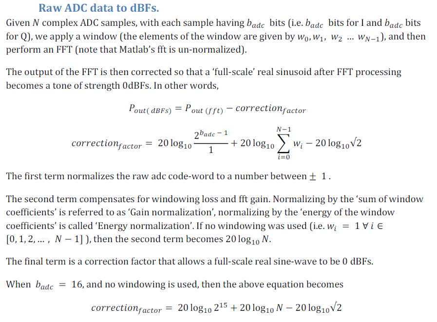
It is at this point I am stuck.If I normalize this data by dividing it by 16,384 I now have unit-less numbers but can not find any helpful documentation on how to map these values to power measurements. I did find a document on the forums "7367.RadarStudio_matlab_scaling.pdf" that provides some equations but when applying these equations to the data the values on my heatmap still make no sense. Below is a snip of the equations.

I feel that this is an easy issue to correct, I just can't seem to find the correct conversion to go from ADC bit count units to physical units.

Attached here is one example of me trying to apply a some variant of this correction factor to the data. This frame has a target that matches the location it was found in the TI GUI but you can see my units are very wrong. Don't worry about the mirror image, I have not windowed or applied anything to clean up the data yet.

Any info you could provide would be useful.

Ted

  • EDIT:

    Figure 1 should have been this image

  • Hi,

    Are you trying to compute the Received Power similar to the questions in this thread?

    Thank you

    Cesar

  • Cesar, 

    I have seen a few of these posts before and they seem to not answer the question I am asking. I understand that if you normalize the ADC data and FFT, the result is unit-less but then you need to convert that value to physical units for say a SNR of power. 

    Say we were building a thermometer with an ADC and we captured 16 bit data that represents temperature but it has been digitized into bits. You wouldn't say since these bits are larger it is hotter over here than over there, you would want to know what temperature we have. So there would be some equation that says since the range of by ADC is so many quantized bits that correspond to the dynamic range of the ADC say +/- 3 Volts, here is the temperature equation to convert bit values to temperature.

    In this case the sensor is an antenna that is capturing voltage across its terminals, so the data is a digitized sine wave with the FMCW modulation we will use to process out radar returns. 

    This post here has the kind of units I would like to see on my plots but I can not find the resources to match. There are some snips of code in there but you have to do some conversion before you FFT to get into dBFs

    https://e2e.ti.com/support/sensors/f/1023/p/792357/2935372#2935372

    Ted

  • Hello Ted,

    Typically for radar detection the  physical unit  used for detection is SNR which is derived by getting ratio of a FFT peak to the noise level in adjacent bins (for example CFAR detection algo) . In this case the absolute value does not matter , just the ratio of the peak to the noise level matters.

    If you are looking at converting the ADC code to some absolute physical value, there are two common references used:

    1) Referencing the ADC code to ADC full scale value (dBFS). You seem to have put the detailed computation of the ADC code to dBFS value in your post above. So I assume that is clear to you.

    2) Reference the ADC code to the absolute signal amplitude at Rx input pin. You can find the computation of that in the following post https://e2e.ti.com/support/sensors/f/1023/t/613223

    Regards,
    Vivek

  • Hello Vivek,

    Thank you for your reply, the link you sent me was one I have never found before. That link explains the upper limit of the ADC voltage rail and what power that translates to. The equations for converting FFT of adc code word values to dBFS in the snapshot I sent was not 100% clear on what part of the FFT to apply but I figured it out on my own. 

    I was more curious if to get a proper value out of those equations did I need to normalize the ADC code word value and then scale it to the range of voltage of the ADC. It sounds like the answer was no and there are separate calculations that I can do if I want to know the signal power detected back at the input of the ADC.

    Ted