This thread has been locked.

If you have a related question, please click the "Ask a related question" button in the top right corner. The newly created question will be automatically linked to this question.

LDC2112: PCB layers、calculator、long press setting、Force touch condition

Part Number: LDC2112
Other Parts Discussed in Thread: LDC1612, LDC2114

Hi Kristin

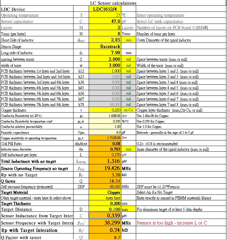
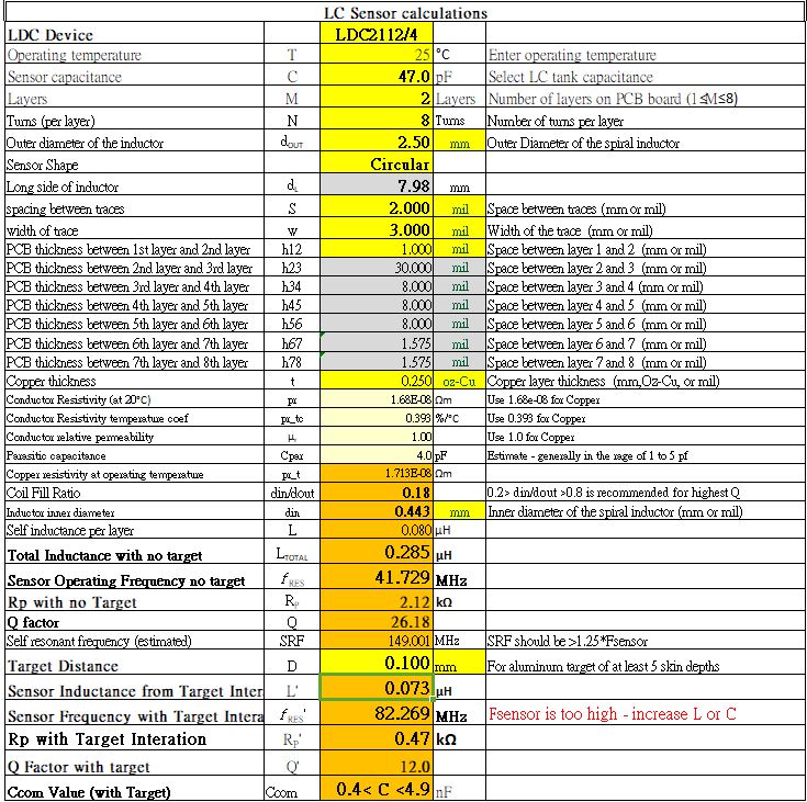
We met the parameter error on the excel, please help it, thanks.

1. How to set the number of seconds for long press? Do you have software documentation?

2. If we have the demand for the force button, what is the mechanism design? How to set the pressure(address 0x18)? How much is the single-button SPS recommended?

3. <<<<We recommend a 0.2mm deflection. I recommend using the Metal Deflection tool in the LDC Tools excel calculator.>>>>Please make sure the red word is a typo? um or mm? because of target distance 0.2mm gap only.

4.Why do I adjust the same parameters as TI but not the same frequency and Rp? Sensor frequency with the target over 10MHz will show increase L or C, why datasheet sample does not show the error?

  • Hi Alex,

    1. Can you clarify what you mean by this question? This is mostly not determined by software. The duration of a button press is based on how long the user holds down the button, your GAIN settings, and your baseline tracking settings. The 50s button timeout is not configurable. If you are looking for more information about how to configure the LDC2112's registers, I suggest this application note.

    2. If you would like to detect the degree of force applied to the button, you will need to read the output data from the DATAx registers. I recommend using at least 40SPS for this type of application. Note that if you do not wish to detect multiple strengths of button presses, you do not need to do this. You can configure the gain and hysteresis settings to detect a specific applied force using the application note in question 1. Note that the force needed to trigger the button may change across temperature, depending how your housing material's rigidity changes across temperature.

    3. Yes, my apologies, this was a typo. We recommend a 0.2um deflection at least. I will edit the previous response.

    4. Can you clarify which versions of the tool you have taken the screenshots from? The reason you are seeing warnings above 10MHz is because you have selected "LDC1612/4" in the LDC Device section. This device has a maximum sensor frequency of 10MHz. If you select the LDC2112/4, the maximum sensor frequency will be 30MHz. You are seeing a difference in the sensor frequency with target interaction between the two screenshots because the target materials are different.

  • Hi Kristin

    1. I want to know if the button is pressed for five seconds and send an interrupt to the MCU as a reset button. it is available?

    4. .I use Calculator_slyc137e zip file, there are two excel files the one is LDC_tools-ext49 the one is excel_FEMM_v1p28.
    I calculated the parameter(fill in the yellow bottom) and got two different frequencies.

    However, compared to the spec example, three frequencies appear. why the excel tool does not sync with specification? please advise, thanks.

  • Hi Alex,

    1. This feature is not available. The MCU would need to keep track of how long the button is pressed based on the OUTx assertions.

    4. In the two screenshots you shared, the outer diameter of the coil is slightly different. If you adjust them to the same value do you still see different frequencies?

    Best Regards,

  • Hi Kristin

    4. Thank you for your correction, but it is still different from the specifications, even if the parameters are the same.

  • Hello Alex,

    I suspect that the differences are due to the way parasitic capacitance is handled in the two different calculators; the difference was due to an oversight, but honestly isn't that big a deal for sensors within the operating region of the LDC2114. The differences between the two calculators will be more pronounced with small sensor inductances and capacitances, but since those sensors don't work with the LDC, it doesn't really matter. 

    Your sensor doesn't look like it can work with the LDC2114. The FEMM calculator is more accurate, so unless the FEMM simulation shows you are within the 30MHz max operating frequency for the LDC2114, you need to redesign your sensor.

    If the FEMM tool shows that you can use this sensor and you decide to use this sensor, you will need to be thorough in analyzing it across temperature and component tolerances to make sure that you have some margin. 

    Regards,

    ChrisO