This thread has been locked.
If you have a related question, please click the "Ask a related question" button in the top right corner. The newly created question will be automatically linked to this question.
The LM35 datasheet specifies absolute min/max output voltage as -1/+6 V. However, the absolute max junction temperature is 150 C, so:
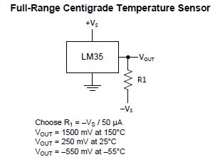
1. How could the LM35 ever drive the Vout pin higher than +1.5 V (10 mV x 150 C), let alone anywhere near +6 V?
Similarly, I presume the operating temperature must never fall below the absolute min storage temperature of -65 C (resulting in Vout = -650 mV), so:
2: Under what circumstances would a normally-operating LM35 allow Vout to be pulled below -650 mV, let alone down to -1 V (assuming absolute max output current not violated)?
If the LM35 cannot output -1 or +6 V itself, I assume these limits are relevant only when Vout is externally driven.
For example, when the LM35 is powered, it seems like it would be safe to connect Vout to +5 V because Vout can only source current, and +5 V doesn't exceed the absolute max +6 V.
3. Is this correct?
4. Is this still safe to do when the LM35 is unpowered?
Finally, when the LM35 is unpowered:
5. Is it safe to externally drive Vout to a negative voltage (e.g. -500 mV) which does not violate the absolute min -1 V?
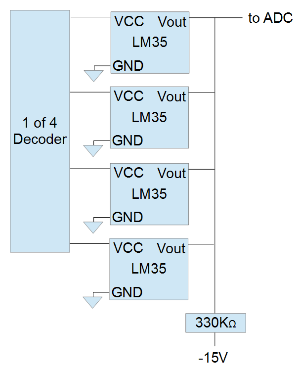
I'm asking these questions because I want to multiplex four LM35 outputs in the following way.
Jim,
To address the Abs Max ratings, this is more of a process definition and is indicative of the limit of the process. Think of it more as a safety precaution of our device in case of failure. Even if through proper operation of the device it would not reach these Abs Max ratings. With this in mind, I am wondering why in your schematic you have the devices outputs pulled down to -15V? Although there is a shunt resistor, this would violate our abs max min of -1V.
In the datasheet, there is no indication that having Vout at -5V should be an issue. Would this be the same voltage as the supply? I would need to test and verify whether there could be some back current that could power the device if Vout is sitting on a higher rail than Vsupply even when device is unpowered. Although I doubt this to be the case.
Jalen
Jim,
I understand your schematic. I don't think you should run into any issues, but I would verify that there is not back current powering the device when unpowered (Vcc = 0V). It seems like you may have tested for this though. This implementation should be fine.
Jalen