Part Number: AWR1642BOOST
Other Parts Discussed in Thread: AWR1642,
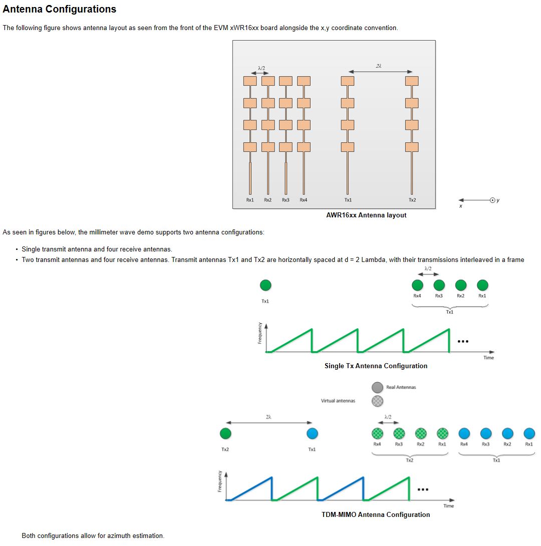
AWR1642 MMW Demo uses two TX antennas to double the number of angle bins in the range-azimuth heat map. The explanation
for MIMO processing assumes that the distance between TX antennas is four times the distance between the receiver
antennas, allowing to create the "virtual receiver" array of 8 antennas. However, the distance between TX antennas on
the board does not seem to be equal to four times the interval between the RX antennas
1) Could you point out the exact specification of AWR1642Boost antenna geometry? I assume that
design schematics for the board have that info, but they are in the Altium designer format, not that easy to view on Linux
2) Does the "heat map" calculation in MMW demo firmware performs simple fft along the receivers to resolve the angles, or
is some more complicated algorithm employed?
3) If it is fft, do you perform some correction for the nonuniform spacing between the MIMO "virtual antennas"
due to the distance between TX antennas not equal to four times the distance between the RX antennas?
Thank you for any help.
Mikhail