Because of the holidays, TI E2E™ design support forum responses will be delayed from Dec. 25 through Jan. 2. Thank you for your patience.

This thread has been locked.

If you have a related question, please click the "Ask a related question" button in the top right corner. The newly created question will be automatically linked to this question.

CCS/IWR6843: IWR6843 MIMO with Antenna arrangement

Part Number: IWR6843

Tool/software: Code Composer Studio

Dear TI 

We have design a module with fully 4G Bandwidth antenna at 60GHz. 

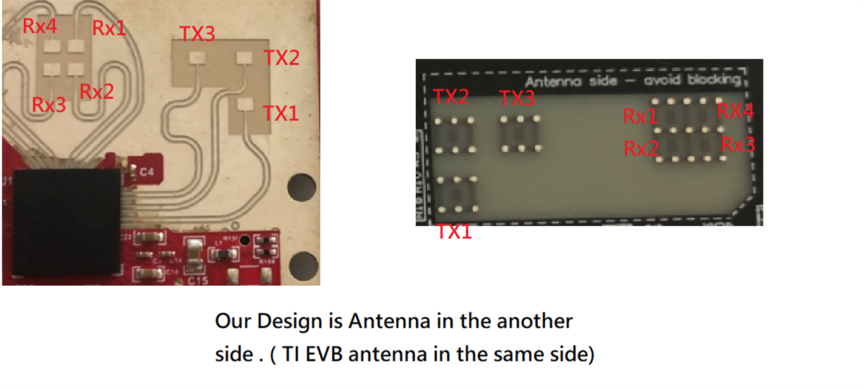
But our antena architecture is in the back side , TI EVB is in the same sie. 

The location is the same but output side is different , which part need to be modify for MIMO in the source code ? 

Our reference lab is the 3D people counting at industrial toolbox 4.2 . can help ?

We check the antenna arragement as below diagram , please help how to modify parameter for this case.  

  • Agate Ko,

        As long as Antenna mappings are the same and distance between receiver Antennas are lamda/2  and Transmitter antenna are lamda then you should be able to use the same demo configuration for the Angle estimation. 

    You could refer to below post as well for understanding the code for virtual antenna configuration.

    https://e2e.ti.com/support/sensors/f/1023/t/854133

    Thanks and regards,

    CHETHAN KUMAR Y.B.

  • Dear  CHETHAN KUMAR Y.B. Sir


          Your link is my before Q&A case .  

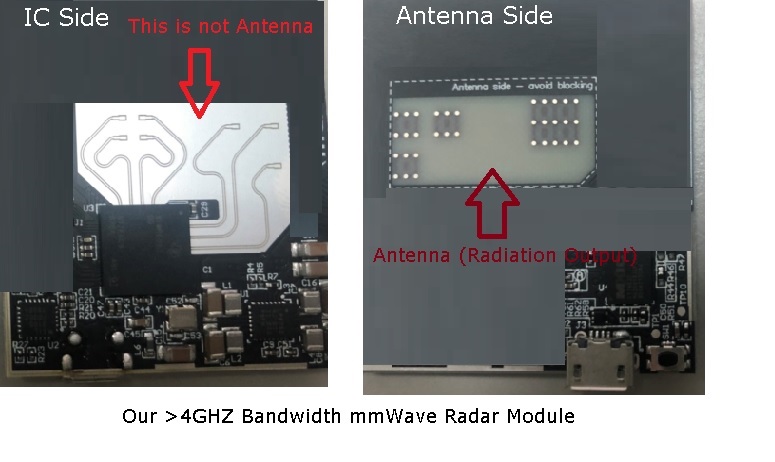
          Below is our module with 6843 , the antenna part is not the same with TI EVB , It's antenna radiation output from another side. (Not in the IC side) 

          When we use the same demo configuration for the angle estimation is OK ?  Horizontal element direction is swapped . Why it is ok ?  

          Can help me to figure out  why ? 

          ( This antenna architecture gain & bandwidth & heat issue can improve very much for CMOS mmwave)


  • Dear  CHETHAN KUMAR Y.B. Sir

    Can help us ?  The field test is the horizontal direction swapped , how to modify the detial function for this antenna design ?

    BR 

  • Agate Ko,

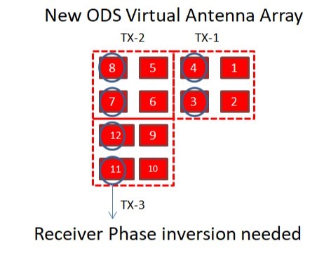
          Sorry for the delay in response,  In the original ODS EVM virtual antenna position is shown below. 

    In the new ODS antenna virtual antenna array would be mirror imaged and receiver phase inversion seem to be at different location 

    You could modify the OOBdemo_angleEstimationAzimElev below E2E thread has the link, 

    https://e2e.ti.com/support/sensors/f/1023/t/854133

    Thanks and regards,

    CHETHAN KUMAR Y.B.