This thread has been locked.

If you have a related question, please click the "Ask a related question" button in the top right corner. The newly created question will be automatically linked to this question.

CCS/IWR6843: SPI test compile error

Part Number: IWR6843
Other Parts Discussed in Thread: MMWAVEICBOOST, UNIFLASH

Tool/software: Code Composer Studio

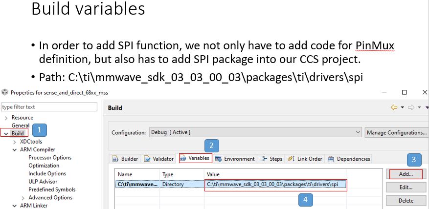
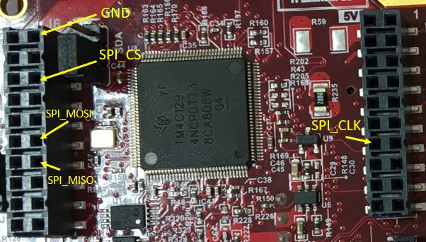
I'm trying to test SPI function on IWR6843. After finished pinmux settings, I modified the mss_main.c code of 3D people counting and added the SPI test code based on sample code in the path: C:\ti\mmwave_sdk_03_03_00_03\packages\ti\drivers\spi\test\xwr68xx

I already done SPI_init(), SPI_Params_init(&params);

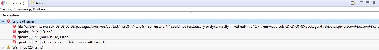
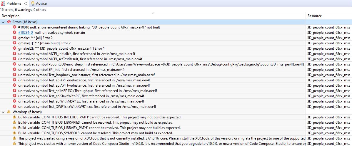
But there were many errors occurred. Please explain (something like 3D_people_count_68xx_mss.xe4f not built, other errors and help me solve it.

Here's the code I used

void Test_spiSlaveWithPC(void)
{
    SPI_Params     params;
    SPI_Handle     handle;
    spiTestMsg*    pTestMsg;
    uint16_t       retry=0;
    uint16_t       msgSeqNo = 0;
    uint32_t       loop;
    volatile uint32_t  cycles;
    float          throughput;
    uint32_t       totalLoop;

    /* Setup the default SPI Parameters */
    SPI_Params_init(&params);

    params.mode = SPI_SLAVE;
    params.frameFormat = SPI_POL0_PHA1;
    params.pinMode = SPI_PINMODE_4PIN_CS;
    params.shiftFormat = SPI_MSB_FIRST;

    /* When communicating with PC through FTDI, it is difficult to toggle CS for every two bytes, hence set csHold to 1.
       In this mode, the highest working SPI clock is 2MHz */
    params.csHold = 1;

    /* Enable DMA and set DMA channels */
    params.dmaEnable = 1;
    params.dmaHandle = gDmaHandle;
    params.u.slaveParams.dmaCfg.txDmaChanNum =1U;
    params.u.slaveParams.dmaCfg.rxDmaChanNum =0U;

    handle = SPI_open(0, &params);
    if (handle == NULL)
    {
        System_printf("Error: Unable to open the SPI Instance\n");
        MCPI_setFeatureTestResult ("SPI Slave with PC ", MCPI_TestResult_FAIL);
        return;
    }

    memset((void *)txBuf, 0x55, SPI_TEST_MSGLEN);

    System_printf("Debug: SPI Instance %p has been reopened in SLAVE mode successfully for 4pin FTDI testing\n", handle);
    gXWR1xxxSlaveReady = true;

    while(1)
    {
        Test_spiRead(handle, SPI_TEST_MSGLEN, (void *)rxBuf, 0U);

        pTestMsg = (spiTestMsg*)&rxBuf[0];
        if(pTestMsg->magicNumber  != SWAP_BYTES(MAGIC_NUMBER))
        {
            System_printf("incorrect magic Number: 0x%x 0x%x\n", pTestMsg->magicNumber, SWAP_BYTES(MAGIC_NUMBER));
            continue;
        }

        if((pTestMsg->dataLen != SWAP_BYTES(SPI_TEST_SYNC_MSGLEN)) || (pTestMsg->seqNo != 0))
        {
            System_printf("incorrect datalen(%d), seqNo= %d\n", pTestMsg->dataLen, pTestMsg->seqNo);
            continue;
        }

        /* Got the correct sync message, send back the message */
        msgSeqNo = SWAP_BYTES(pTestMsg->seqNo);
        pTestMsg->seqNo = SWAP_BYTES(msgSeqNo+1);

        /* Read two byte , send it back */
        Test_spiWrite(handle, SPI_TEST_MSGLEN, (void *)pTestMsg, 0U);

        break;
    }

    /* Save the Sync message for re-sent */
    memcpy((void *)txBuf, (void *)pTestMsg, SPI_TEST_MSGLEN);

    /* Got the Sync message, waiting for next test message */
    msgSeqNo += 2;

    /* Test loop count from first 16 bits of Sync message */
    loop = pTestMsg->data[0] * 256 + pTestMsg->data[1] ;
    System_printf("Test loop=%d, bufferLen=%d\n", loop, SPI_TEST_MSGLEN);
    totalLoop = loop;

    while(loop)
    {
        /* Read two byte , send it back */
        Test_spiRead(handle, SPI_TEST_MSGLEN, (void *)rxBuf, 0U);

        if(pTestMsg->magicNumber != SWAP_BYTES(MAGIC_NUMBER))
        {
            continue;
        }

        if((pTestMsg->seqNo == 0) && (pTestMsg->dataLen == SWAP_BYTES(SPI_TEST_SYNC_MSGLEN)))
        {
            /* Re-sent the Sync message */
            Test_spiWrite(handle, SPI_TEST_MSGLEN, (void *)txBuf, 0U);
            continue;
        }

        /* Receive Last message */
        if(pTestMsg->seqNo == SWAP_BYTES(msgSeqNo - 2))
        {
            Test_spiWrite(handle, SPI_TEST_MSGLEN, (void *)txBuf, 0U);
            retry++;

            continue;
        }

        /* Incorrect seqNo, drop the message */
        if(pTestMsg->seqNo != SWAP_BYTES(msgSeqNo))
        {
            retry++;
            continue;
        }

        if(loop == totalLoop)
        {
            // Start the counter after receive the first message
            Test_benchmarkStart(0);
        }

        retry = 0;
        loop--;

        /* Receive the message with correct header, increment the seq Number */
        pTestMsg->seqNo = SWAP_BYTES(SWAP_BYTES(pTestMsg->seqNo) + 1);

        Test_spiWrite(handle, SPI_TEST_MSGLEN, (void *)pTestMsg, 0U);

        msgSeqNo += 2;
    }
    // Stop the counter
    cycles = Test_benchmarkStop(0);

    // Calculate and print the count
    throughput = 8.0 * SPI_TEST_MSGLEN * totalLoop  * VBUSP_FREQ / cycles;
    System_printf("Debug: throughput overall = %.2f Mbps\n", throughput);

    MCPI_setFeatureTestResult ("SPI Slave with PC ", MCPI_TestResult_PASS);
}

/**
 *  @b Description
 *  @n
 *      System Initialization Task which initializes the various
 *      components in the system.
 *
 *  @retval
 *      Not Applicable.
 */
static void Pcount3DDemo_initTask(UArg arg0, UArg arg1)
{
    int32_t             errCode;
    MMWave_InitCfg      initCfg;
    UART_Params         uartParams;
    Task_Params         taskParams;
    Semaphore_Params    semParams;
    DPM_InitCfg         dpmInitCfg;
    DMA_Params          dmaParams;
    DMA_Handle          dmaHandle;
	SPI_Params     		params;
    SPI_Handle     		handle;
	SOC_Handle      	socHandle;
    spiTestMsg*    		pTestMsg;
	int32_t         	retVal = 0;
	
	/* Get SOC driver Handle */
    socHandle = (SOC_Handle) arg0;

    DPC_ObjectDetectionRangeHWA_InitParams objDetInitParams;
//    int32_t             i;

    /* Debug Message: */
    System_printf("Debug: Launched the Initialization Task\n");
	
	/* Initialize MCPI logger framework */
    MCPI_Initialize ();

    /*****************************************************************************
     * Initialize the mmWave SDK components:
     *****************************************************************************/
    /* Initialize the UART */
    UART_init();

    /* Initialize the DMA for UART */
    DMA_init ();
	
	/* Open DMA driver instance 0 for SPI test */
    gDmaHandle = DMA_open(0, &dmaParams, &retVal);

    if(gDmaHandle == NULL)
        {
        printf("Open DMA driver failed with error=%d\n", retVal);
        return;
    }
	
	/* Initialize the SPI */
    SPI_init();
	/* Setup the default SPI Parameters */
    SPI_Params_init(&params);
	
	/**************************************************************************
     * Test: One instace API test - SPIA
     **************************************************************************/
    Test_spiAPI_oneInstance(0);
    System_printf("Debug: Finished API Test for SPIA!\n");

        /**************************************************************************
     * Test: One instace API test - SPIB
         **************************************************************************/
    Test_spiAPI_oneInstance(1);
    System_printf("Debug: Finished API Test for SPIB!\n");

        /**************************************************************************
     * Test: two instaces API test - SPIA & SPIB
         **************************************************************************/
    Test_spiAPI_twoInstance();
    System_printf("Debug: Finished API Test for SPIA + SPIB!\n");
	
	if(gXWR1xxxSlaveWithFTDITest)
    {
        /* Enable output control for SPIA in 4Pin mode */
        if(SOC_SPIOutputCtrl(socHandle, 0U, 0U, &errCode) < 0)
        {
            /* Debug Message: */
            System_printf ("Debug: SOC_SPIOutputCtrl failed with Error [%d]\n", errCode);
            return;
        }

        Test_spiSlaveWithPC();
    }

    /* Open the DMA Instance */
    DMA_Params_init(&dmaParams);
    dmaHandle = DMA_open(0, &dmaParams, &errCode);
    if (dmaHandle == NULL)
    {
        printf ("Error: Unable to open the DMA Instance [Error code %d]\n", errCode);
        return;
    }

    /* Initialize the GPIO */
    GPIO_init();

    /* Initialize the Mailbox */
    Mailbox_init(MAILBOX_TYPE_MSS);

    /* Platform specific configuration */
    Pcount3DDemo_platformInit(&gMmwMssMCB.cfg.platformCfg);

    /*****************************************************************************
     * Open the mmWave SDK components:
     *****************************************************************************/
    /* Setup the default UART Parameters */
    UART_Params_init(&uartParams);
    uartParams.clockFrequency = gMmwMssMCB.cfg.platformCfg.sysClockFrequency;
    uartParams.baudRate       = gMmwMssMCB.cfg.platformCfg.commandBaudRate;
    uartParams.isPinMuxDone   = 1;

    /* Open the UART Instance */
    gMmwMssMCB.commandUartHandle = UART_open(0, &uartParams);
    if (gMmwMssMCB.commandUartHandle == NULL)
    {
        Pcount3DDemo_debugAssert (0);
        return;
    }

    /* Setup the default UART Parameters */
    UART_Params_init(&uartParams);
    uartParams.writeDataMode = UART_DATA_BINARY;
    uartParams.readDataMode = UART_DATA_BINARY;
    uartParams.clockFrequency = gMmwMssMCB.cfg.platformCfg.sysClockFrequency;
    uartParams.baudRate       = gMmwMssMCB.cfg.platformCfg.loggingBaudRate;
    uartParams.isPinMuxDone   = 1U;

    uartParams.dmaHandle      = dmaHandle;
    uartParams.txDMAChannel   = UART_DMA_TX_CHANNEL;  
    uartParams.rxDMAChannel   = UART_DMA_RX_CHANNEL;  

    /* Open the Logging UART Instance: */
    gMmwMssMCB.loggingUartHandle = UART_open(1, &uartParams);
    if (gMmwMssMCB.loggingUartHandle == NULL)
    {
        System_printf("Error: Unable to open the Logging UART Instance\n");
        Pcount3DDemo_debugAssert (0);
        return;
    }

    /* Create binary semaphores which is used to signal DPM_start/DPM_stop/DPM_ioctl is done
     * to the sensor management task. The signalling (Semaphore_post) will be done
     * from DPM registered report function (which will execute in the DPM execute task context). */
    Semaphore_Params_init(&semParams);
    semParams.mode              = Semaphore_Mode_BINARY;
    gMmwMssMCB.DPMstartSemHandle   = Semaphore_create(0, &semParams, NULL);
    gMmwMssMCB.DPMstopSemHandle   = Semaphore_create(0, &semParams, NULL);
    gMmwMssMCB.DPMioctlSemHandle   = Semaphore_create(0, &semParams, NULL);

    /* Open EDMA driver */
    Pcount3DDemo_edmaInit(&gMmwMssMCB.dataPathObj, DPC_OBJDET_R4F_EDMA_INSTANCE);

    /* Use EDMA instance 0 on MSS */
    Pcount3DDemo_edmaOpen(&gMmwMssMCB.dataPathObj, DPC_OBJDET_R4F_EDMA_INSTANCE);

    Pcount3DDemo_hwaInit(&gMmwMssMCB.dataPathObj);
    Pcount3DDemo_hwaOpen(&gMmwMssMCB.dataPathObj, gMmwMssMCB.socHandle);

    /*****************************************************************************
     * mmWave: Initialization of the high level module
     *****************************************************************************/

    /* Initialize the mmWave control init configuration */
    memset ((void*)&initCfg, 0 , sizeof(MMWave_InitCfg));

    /* Populate the init configuration: */
    initCfg.domain                  = MMWave_Domain_MSS;
    initCfg.socHandle               = gMmwMssMCB.socHandle;
    initCfg.eventFxn                = Pcount3DDemo_eventCallbackFxn;
    initCfg.linkCRCCfg.useCRCDriver = 1U;
    initCfg.linkCRCCfg.crcChannel   = CRC_Channel_CH1;
    initCfg.cfgMode                 = MMWave_ConfigurationMode_FULL;
    initCfg.executionMode           = MMWave_ExecutionMode_ISOLATION;

    /* Initialize and setup the mmWave Control module */
    gMmwMssMCB.ctrlHandle = MMWave_init (&initCfg, &errCode);
    if (gMmwMssMCB.ctrlHandle == NULL)
    {
        /* Error: Unable to initialize the mmWave control module */
        System_printf ("Error: mmWave Control Initialization failed [Error code %d]\n", errCode);
        Pcount3DDemo_debugAssert (0);
        return;
    }
    System_printf ("Debug: mmWave Control Initialization was successful\n");

    /* Synchronization: This will synchronize the execution of the control module
     * between the domains. This is a prerequiste and always needs to be invoked. */
    if (MMWave_sync (gMmwMssMCB.ctrlHandle, &errCode) < 0)
    {
        /* Error: Unable to synchronize the mmWave control module */
        System_printf ("Error: mmWave Control Synchronization failed [Error code %d]\n", errCode);
        Pcount3DDemo_debugAssert (0);
        return;
    }
    System_printf ("Debug: mmWave Control Synchronization was successful\n");
	
	// Create a task to do SPI 
/*	Task_Params_init(&taskParams);
    taskParams.stackSize = 6*1024;
    taskParams.arg0 = (UArg)socHandle;
    Task_create(Test_initTask, &taskParams, NULL);*/

    /*****************************************************************************
     * Launch the mmWave control execution task
     * - This should have a higher priroity than any other task which uses the
     *   mmWave control API
     *****************************************************************************/
    Task_Params_init(&taskParams);
    taskParams.priority  = MMWDEMO_MMWAVE_CTRL_TASK_PRIORITY;
    taskParams.stackSize = 2800;
    gMmwMssMCB.taskHandles.mmwaveCtrl = Task_create(Pcount3DDemo_mmWaveCtrlTask, &taskParams, NULL);


    /*****************************************************************************
         * Create a task to do DMA based UART data transfer
    *****************************************************************************/
    /* Create a binary semaphore for application task to pend */
    Semaphore_Params_init(&semParams);
    semParams.mode = Semaphore_Mode_BINARY;
    gMmwMssMCB.uartTxSemHandle = Semaphore_create(0, &semParams, NULL);

    Task_Params_init(&taskParams);
    taskParams.priority = MMWDEMO_UARTTX_TASK_PRIORITY;
    taskParams.stackSize = 800;
    Task_create(MmwDemo_uartTxTask, &taskParams, NULL);

    /*****************************************************************************
     * Initialization of the DPM Module:
     *****************************************************************************/
    memset ((void *)&objDetInitParams, 0, sizeof(DPC_ObjectDetectionRangeHWA_InitParams));

    /* Note this must be after Pcount3DDemo_dataPathOpen() above which opens the hwa */
    objDetInitParams.L3ramCfg.addr = (void *)&gMmwL3[0];
    objDetInitParams.L3ramCfg.size = sizeof(gMmwL3);
    objDetInitParams.CoreLocalRamCfg.addr = &gDPCTCM[0];
    objDetInitParams.CoreLocalRamCfg.size = sizeof(gDPCTCM);
    objDetInitParams.edmaHandle = gMmwMssMCB.dataPathObj.edmaHandle;
    objDetInitParams.hwaHandle = gMmwMssMCB.dataPathObj.hwaHandle;

    /* DPC Call-back config */
    objDetInitParams.processCallBackFxn.processInterFrameBeginCallBackFxn =
        Pcount3DDemo_DPC_ObjectDetection_processInterFrameCallBackFxn;

    objDetInitParams.processCallBackFxn.processFrameBeginCallBackFxn =
        Pcount3DDemo_DPC_ObjectDetection_processFrameBeginCallBackFxn;

    /* Setup the configuration: */
    memset ((void *)&dpmInitCfg, 0, sizeof(DPM_InitCfg));
    dpmInitCfg.socHandle        = gMmwMssMCB.socHandle;
    dpmInitCfg.ptrProcChainCfg  = &gDPC_ObjDetRangeHWACfg;;
    dpmInitCfg.instanceId       = DPC_OBJDET_R4F_INSTANCEID;
    dpmInitCfg.domain           = DPM_Domain_DISTRIBUTED;
    dpmInitCfg.reportFxn        = Pcount3DDemo_DPC_ObjectDetection_reportFxn;
    dpmInitCfg.arg              = &objDetInitParams;
    dpmInitCfg.argSize          = sizeof(DPC_ObjectDetectionRangeHWA_InitParams);

    /* Initialize the DPM Module: */
    gMmwMssMCB.objDetDpmHandle = DPM_init (&dpmInitCfg, &errCode);
    if (gMmwMssMCB.objDetDpmHandle == NULL)
    {
        System_printf ("Error: Unable to initialize the DPM Module [Error: %d]\n", errCode);
        Pcount3DDemo_debugAssert (0);
        return;
    }

    /* Synchronization: This will synchronize the execution of the datapath module
     * between the domains. This is a prerequiste and always needs to be invoked. */
    while (1)
    {
        int32_t syncStatus;

        /* Get the synchronization status: */
        syncStatus = DPM_synch (gMmwMssMCB.objDetDpmHandle, &errCode);
        if (syncStatus < 0)
        {
            /* Error: Unable to synchronize the framework */
            System_printf ("Error: DPM Synchronization failed [Error code %d]\n", errCode);
            Pcount3DDemo_debugAssert (0);
            return;
        }
        if (syncStatus == 1)
        {
            /* Synchronization acheived: */
            break;
        }
        /* Sleep and poll again: */
        Task_sleep(1);
    }

#ifdef TRACKERPROC_EN
    /*****************************************************************************
         * Create a task to run tracker DPU at lower priority than HWA DPC
    *****************************************************************************/
    /* Create a binary semaphore for application task to pend */
    Semaphore_Params_init(&semParams);
    semParams.mode = Semaphore_Mode_BINARY;
    gMmwMssMCB.trackerDPUSemHandle = Semaphore_create(0, &semParams, NULL);

    Task_Params_init(&taskParams);
    taskParams.priority = MMWDEMO_TRACKERDPU_TASK_PRIORITY;
    taskParams.stackSize = 7*1024;
    Task_create(MmwDemo_trackerDPUTask, &taskParams, NULL);
#endif

    /* Launch the DPM Task */
    Task_Params_init(&taskParams);
    taskParams.priority  = MMWDEMO_DPC_OBJDET_DPM_TASK_PRIORITY;
    taskParams.stackSize = 7*1024;
    gMmwMssMCB.taskHandles.objDetDpmTask = Task_create(mmwDemo_mssDPMTask, &taskParams, NULL);

    /*****************************************************************************
     * Initialize the Profiler
     *****************************************************************************/
    Cycleprofiler_init();

    /*****************************************************************************
     * Initialize the CLI Module:
     *****************************************************************************/
    Pcount3DDemo_CLIInit(MMWDEMO_CLI_TASK_PRIORITY);

    return;
}

int main(void)
{
    /*=======================================
     * Setup the PINMUX to bring out the MibSpiA
     *=======================================*/
    /* NOTE: Please change the following pin configuration according
            to EVM used for the test */

    /* SPIA_MOSI */
    Pinmux_Set_OverrideCtrl(SOC_XWR68XX_PIND13_PADAD, PINMUX_OUTEN_RETAIN_HW_CTRL, PINMUX_INPEN_RETAIN_HW_CTRL);
    Pinmux_Set_FuncSel(SOC_XWR68XX_PIND13_PADAD, SOC_XWR68XX_PIND13_PADAD_SPIA_MOSI);

    /* SPIA_MISO */
    Pinmux_Set_OverrideCtrl(SOC_XWR68XX_PINE14_PADAE, PINMUX_OUTEN_RETAIN_HW_CTRL, PINMUX_INPEN_RETAIN_HW_CTRL);
    Pinmux_Set_FuncSel(SOC_XWR68XX_PINE14_PADAE, SOC_XWR68XX_PINE14_PADAE_SPIA_MISO);

    /* SPIA_CLK */
    Pinmux_Set_OverrideCtrl(SOC_XWR68XX_PINE13_PADAF, PINMUX_OUTEN_RETAIN_HW_CTRL, PINMUX_INPEN_RETAIN_HW_CTRL);
    Pinmux_Set_FuncSel(SOC_XWR68XX_PINE13_PADAF, SOC_XWR68XX_PINE13_PADAF_SPIA_CLK);

    /* SPIA_CS */
    Pinmux_Set_OverrideCtrl(SOC_XWR68XX_PINE15_PADAG, PINMUX_OUTEN_RETAIN_HW_CTRL, PINMUX_INPEN_RETAIN_HW_CTRL);
    Pinmux_Set_FuncSel(SOC_XWR68XX_PINE15_PADAG, SOC_XWR68XX_PINE15_PADAG_SPIA_CSN);

    /* SPI_HOST_INTR - not used, reference code */
    Pinmux_Set_OverrideCtrl(SOC_XWR68XX_PINP13_PADAA, PINMUX_OUTEN_RETAIN_HW_CTRL, PINMUX_INPEN_RETAIN_HW_CTRL);
    Pinmux_Set_FuncSel(SOC_XWR68XX_PINP13_PADAA, SOC_XWR68XX_PINP13_PADAA_SPI_HOST_INTR);

    /*=======================================
     * Setup the PINMUX to bring out the MibSpiB
     *=======================================*/
    /* NOTE: Please change the following pin configuration according
            to EVM used for the test */

    /* Setup the PINMUX to bring out the MibSpiB */
    Pinmux_Set_OverrideCtrl(SOC_XWR68XX_PINF13_PADAH, PINMUX_OUTEN_RETAIN_HW_CTRL, PINMUX_INPEN_RETAIN_HW_CTRL);
    Pinmux_Set_FuncSel(SOC_XWR68XX_PINF13_PADAH, SOC_XWR68XX_PINF13_PADAH_SPIB_MOSI);

    Pinmux_Set_OverrideCtrl(SOC_XWR68XX_PING14_PADAI, PINMUX_OUTEN_RETAIN_HW_CTRL, PINMUX_INPEN_RETAIN_HW_CTRL);
    Pinmux_Set_FuncSel(SOC_XWR68XX_PING14_PADAI, SOC_XWR68XX_PING14_PADAI_SPIB_MISO);

    Pinmux_Set_OverrideCtrl(SOC_XWR68XX_PINF14_PADAJ, PINMUX_OUTEN_RETAIN_HW_CTRL, PINMUX_INPEN_RETAIN_HW_CTRL);
    Pinmux_Set_FuncSel(SOC_XWR68XX_PINF14_PADAJ, SOC_XWR68XX_PINF14_PADAJ_SPIB_CLK);

    Pinmux_Set_OverrideCtrl(SOC_XWR68XX_PINH14_PADAK, PINMUX_OUTEN_RETAIN_HW_CTRL, PINMUX_INPEN_RETAIN_HW_CTRL);
    Pinmux_Set_FuncSel(SOC_XWR68XX_PINH14_PADAK, SOC_XWR68XX_PINH14_PADAK_SPIB_CSN);


    /* SPIB signals are connected to PMIC and XDS110 , unless the connection is removed on XWR16
       EVM, SPI signals can not be enabled as output. */
#if 0
    /* Enable output control for SPIB */
    if(SOC_SPIOutputCtrl(socHandle, 1U, 1U, &errCode) < 0)
    {
        /* Debug Message: */
        System_printf ("Debug: SOC_SPIOutputCtrl failed with Error [%d]\n", errCode);
        goto Exit;
    }
#endif

    /* SPIA DMA and interrupt signals are muxed with other IPs in the SOC.
     * Map them to SPIA.
     */
    if (SOC_selectDMARequestMapping(socHandle, SOC_MODULE_SPIA, &errCode) < 0)
    {
        /* Debug Message: */
        System_printf ("Debug: SOC_selectDMARequestMapping (SPIA) failed with Error [%d]\n", errCode);
        goto Exit;
    }
    if (SOC_selectInterruptRequestMapping(socHandle, SOC_MODULE_SPIA, &errCode) < 0)
    {
        /* Debug Message: */
        System_printf ("Debug: SOC_selectInterruptRequestMapping (SPIA) failed with Error [%d]\n", errCode);
        goto Exit;
    }

    /* Debug Message: */
    System_printf ("**********************************************\n");
    System_printf ("Debug: Launching the MMW Demo on MSS\n");
    System_printf ("**********************************************\n");

    /* Initialize the Task Parameters. */
    Task_Params_init(&taskParams);
    gMmwMssMCB.taskHandles.initTask = Task_create(Pcount3DDemo_initTask, &taskParams, NULL);

    /* Start BIOS */
    BIOS_start();
Exit:
    return 0;    
}

  • Hi Hector,

    Your errors are all unresolved symbols. This means the linker cannot find a compiled version of the functions you are trying to use. For example, one of your errors is "Unresolved Symbol: SPI_init()" - this means that the SPI library isn't properly included or linked. Please check the following:

    • SPI and other new libraries are included in the relevant files
    • SPI and other new libraries have a path in linker properties.
      • Right click on the CCS project
      • Select Properties at the bottom
      • Select linker on the left
      • Ensure there is a path in the linker setting to spi lib

    Regards,

    Justin

  • Hi Justin,

    I added spi lib path to the project but compile still got the same error. Please show me how to solve it with illustration photo.

  • Hi Justin,

    I also tried another method to add library by clicking to mss project ->Properties->Add files. Then I chose libspi_xwr68xx.aer4f in the path C:\ti\mmwave_sdk_03_03_00_03\packages\ti\drivers\spi\lib.

    But it still showed 

    #10010 null: errors encountered during linking; "3D_people_count_68xx_mss.xer4f" not built 3D_people_count_68xx_mss C/C++ Problem

    null: unresolved symbols remain 3D_people_count_68xx_mss C/C++ Problem

    Import a library should be easy. I don't know why it failed.

    Here's the message when I tried to add lib file to project

  • Hi Justin,

    I got less compiling error by adding xwr68xx_spi_mss.xer4f in the path C:\ti\mmwave_sdk_03_03_00_03\packages\ti\drivers\spi\test\xwr68xx to the project.

    Previously, I got 13 compile errors. After added xwr68xx_spi_mss.xer4f, now I only see 4 errors. Not sure whether this is better or not. But even if I don't use SPI function and remove all SPI commands, I still have these 4 errors after adding xwr68xx_spi_mss.xer4f to my project. If I don't add it, I only got compile error when I use SPI commands.
    How to solve it? I expect I can use SPI/I2C within this week, but I got stuck at library linking even though it seems to be easy.

    1. Here's the error after I added xwr68xx_spi_mss.xer4f

    error: "could not be statically or dynamically linked null: file "C:/ti/mmwave_sdk_03_03_00_03/packages/ti/drivers/spi/test/xwr68xx/xwr68xx_spi_mss.xer4f" could not be statically or dynamically linked 3D_people_count_68xx_mss C/C++ Problem

    2. Here's the error without xwr68xx_spi_mss.xer4f, I only added libspi_xwr68xx.aer4f in the path C:\ti\mmwave_sdk_03_03_00_03\packages\ti\drivers\spi\lib

  • Hi Hector,

    You are linking the test library, instead you need to link the functional library. It is at: C:\ti\mmwave_sdk_03_03_00_03\packages\ti\drivers\spi\lib

    You can read mmWave SDK module documentation here: C:\ti\mmwave_sdk_03_03_00_03\docs\mmwave_sdk_module_documentation.html - if you go through the SPI documentation, you can see all external functions, which are the ones you should be using. Do not use the "Test" functions unless you are specifically trying to test the functionality of the module.

    Regards,

    Justin

  • Hi Justin,

    1. I modified my code, there's no compile error now. But I'm not sure how to test SPI function with UART GUI. As my understanding, we must connect PC to FTDI port on MMWAVEICBOOST in order to use SPI, right?

    If it's right, do I need to change S1 switch as below to use FTDI?

    The problem is: after I switched as above and connect PC to FTDI port, I don't see any port number on PC Device Manager to connect device to GUI even though I installed FTDI driver on Windows. How to connect?

    2. I see in test_common.c in the path C:\ti\mmwave_sdk_03_03_00_03\packages\ti\drivers\spi\test\common

    has a function MCPI_setFeatureTestResult ((const char *)&testCase[0], MCPI_TestResult_PASS);

    I think it's to test whether SPI pass or not. But I can't find where its declaration located. Please tell me more about MCPI_setFeatureTestResult if it's really used to test SPI.

    3. How can we send data from IWR6843 to MMWAVEICBOOST via SPI, then send to PC via UART and display on GUI?

    Below is some basic SPI function in my code, but I don't know how to combine it with UART data transfer to check whether SPI works well and display tracking on GUI correctly.

    static int32_t Test_spiReadWrite(const SPI_Handle handle, uint32_t dataLen, void* inBuffer, void* outBuffer, uint8_t slaveIndex)
    {
        SPI_Transaction  transaction;
    
        /* Configure Data Transfer */
        transaction.count = dataLen;
        transaction.txBuf = outBuffer;
        transaction.rxBuf = inBuffer;
        transaction.slaveIndex = slaveIndex;
    
        /* Start Data Transfer */
        if (SPI_transfer(handle, &transaction) != true)
        {
            return -1;
        }
        return 0;
    }
    
    void MmwDemo_mssInitTask(UArg arg0, UArg arg1)
    {
    // UART function
    
       UART_init();
    }
    
    int main(void)
    {
       //handle = SPI_open(someSPI_configIndexValue, &params);
       handle = SPI_open(0, &params);
       if (!handle) {
           System_printf("SPI did not open");
       }
    
       /* Initialize the Task Parameters. */
        Task_Params_init(&taskParams);
        taskParams.priority = 3;
        taskParams.stackSize = 4*1024;
        Task_create(MmwDemo_mssInitTask, &taskParams, NULL);
    }

  • Hi Hector,

    The FTDI port on the ICBOOST is only for mmWave studio direct control. We don't provide a driver for SPI to windows PC interface. To use the SPI connection, you will need to set the device in 40 Pin BP/LP mode, then connect some other device (like a beagle bone raspberry pi) to SPI pins.

    Regarding test code - these are unit tests that can be used to ensure the SPI driver is functioning correctly. Unit test documentation is here: <mmwave_sdk_03_03_00_03>/docs/mmwave_sdk_unit_test_procedure.pdf

    You should not be using any of the test functions in your application.

    Regards,

    Justin

  • Hi Justin,

    I checked mmwave_sdk_unit_test_procedure.pdf as you said. It mentions we can test SPI on PC via FTDI port by setting gXWR1xxxSlaveWithFTDITest = 1.

    But I'm still unclear how to check whether SPI function works well in this case. If I write SPI transfer function correctly, and connect IWR6843 EVM from FTDI port to PC USB port. Then TI GUI can still display tracking ? Or TI GUI for IWR6843 3D people counting is only to demo via UART on XDS110 port and can't read SPI data from FTDI port?

  • Hi Hector,

    I believe Charles answered your questions here: https://e2e.ti.com/support/sensors/f/1023/t/897434 - SPI will come out, but we don't have applications that support it, so you will have to find a python library that parses SPI.

    Regards,

    Justin

  • Hi Justin,

    They told me to use xer4f built in TI SDK. I prefer running program without CCS Debug mode. Because I need to give my customers my program. They are only able to run the program without much effort. If I tell my customers to use xer4f and do all settings to run in CCS Debug mode by themselves, it's inconvenient for them.

    If I want to do SPI communication without running CCS in Debug mode, how to create my own code from TI SDK and burn bin file on IWR6843? I tried to link TI library to CCS project, but it showed: #10010 null... xer4f not built. That's why I have to test SPI by CCS in Debug mode. 

    Please tell me both ways to test SPI by xer4f in CCS Debug Mode and build bin file from SDK->...->driver->SPI folder.

  • Hi Hector,

    CCS Debug mode is for you to debug if something doesn't work. If it compiles and runs in debug mode, it will compile and run in standard mode. Compiling creates both.

    Regards,

    Justin

  • Hi Justin,

    But I see xer4f can only be used in CCS Debug mode. It's easier to generate via gmake command, but I can't burn it to device by Uniflash. Uniflash can only flash bin file. Sadly, bin file is more difficult to generate due to "library not linking" error, even though I linked all paths of library to the project. If it's simple as you thought, I don't need to ask. Please help me check more about the way to link SPI test code to compile successfully.

    Anyways, does gmake command generate xer4f & bin file at once? Which type of image can Uniflash flash?

    In order to avoid "library not linking" error, is it better to generate bin file by gmake command rather than rebuild project on CCS?If so, I only need to modify main_mss.c code and copy to the SDK SPI driver folder to generate new bin file without having to link any path, right?

  • Hi Hector,

    You need to link all libraries to compile anything. Once the .xer4f and .xe674 are generated, these are used to create the .bin. Please check and see if the .xer4f file is actually up to date, and not an old file.

    Regards,

    Justin

  • Hi Justin,

    Please check if this settings are correct for SPI communication between 2 IWR6843 EVMs:

    - S1 dip switch

    1 - off

    2 - on

    3 - off

    4, 5 - on

    6, 7 - off

    8, 9 - on

    10, 11 - off

    12 - on

    - Connect the corresponding pins of 2 EVMs together. Only connect pins GND, CLK, CS, MOSI, MISO on J5 & J6 from EVM1 to corresponding pin on EVM2, right? Don't we need to connect pins 3v3 of each EVM together? As i know, we only need to connect 4 SPI pins for communication. But your colleague - woodall, told me to connect GND pins on J6 connector of 2 EVMs together. So I wanna ask when we need to connect GND, 3v3, 5V pins on J6 connector?

    - How to generate bin file by xer4f file?

    - I linked all library path to project, but it still showed "unresolved symbols remain" error. It's so simple but always happens error.

    By the way, if I connect IWR6843 EVM to Arduino or Rapsberry Pi via SPI, do I need to use any voltage converter board to avoid device broken? I'm not sure about the voltage difference between them. It'd be great if I can connect them directly the same way as between 2 IWR6843 EVMs. But I'm concerned since IWR6843 Input voltage is 5 V, while Arduino Uno is 6-12V. It may cause EVM broken.

  • Hi,

    You connect GND, as GND is relative, and all devices need the same GND reference point for communication to work.

    Second, you can see the projectspec post build steps to understand how to generate a .bin from the .xe files.

    Third, link files. You need to do the following to include a peripheral library:

    1. In the file using SPI, include SPI.h
    2. Ensure the path to SPI.h is properly defined
    3. Link the library file:
      1. You need to set the path to the .lib file. Make sure you select the right .lib, it needs to be the 68xx file.
      2. Make sure you also add the file name in the linked file section of CCS.
      3. Let me know if you don't know how to do this

    The EVM needs a 5V input. So if you connect to another board, you need to make sure the EVM is still powered from the 5V jack. The 5V and 3.3V pins on the device are outputs.

    Regards,

    Justin

  • Hi Justin,

    I'm at home now, so I'll check .lib linking later. As I know, in order to use SPI, we only need to add path of SPI.h. Do u mean file name libspi_xwr68xx.aer4f?

    If so, I added this lib into project long time ago. But I still got compile error. It's not simple as you thought. You can see my photo below. 
    Please tell me another way to solve "library not linking" problem.

    - Regarding devices, if I connect iwr6843 EVM to Rapsberry Pi 3, if the power input of 2 boards are different, do I need to use a level shifter? Is it still ok when we connect SPI signal wires from Pi 3 to TI IWR6843? I think the voltage of each board is not related to SPI wires of each board, right?

  • Hi Hector,

    Your file search path is mostly correct, you don't need "${COM_TI_MMWAVE_INSTALL_DIR}/packages/ti/drivers/spi/" as the link is handled by the line directly below it which links to the lib folder.

    Second, the path "${COM_TI_MMWAVE_INSTALL_DIR}/packages/ti/drivers/spi/" should be included in the Compiler -> Include options tab (depending on how you have included the spi.h file in the source code).

    For the Pi3 and the XWR68 EVM, please ensure the grounds are connected, do not connect the voltage lines, power each one separately for now.

    Regards,

    Justin

  • Hi Justin,

    Can I use TI GUI python code directly on Pi 3 or have to use another version in Linux/Rapsbian OS? Do u have code on Pi 3 to transfer data from SPI_read to UART_write to GUI? Please support me for demo after I transfer SPI data from 6843 to pi 3, then I need to demo via Pi 3 UART.

  • Hi Justin,

    Can you explain why the xwr68xx demo code can work well with UART_writepolling() but when I added SPI_write into demo code and set it as SPI_SLAVE mode, SPI_write didn't work?

    e.g.

    static int32_t spi_Write(const SPI_Handle handle, void* buffer, uint32_t dataLen)
    {
        SPI_Transaction transaction;
    
        /* Configure Data Transfer */
        transaction.count = dataLen;
        transaction.txBuf = buffer;
        transaction.rxBuf = NULL;
        transaction.slaveIndex = 0;
    
        /* Start Data Transfer */
        if (SPI_transfer(handle, &transaction) != true)
        {
            return -1;
        }
        return 0;
    }
    
    void SPI_to_UART()
    {
    UART_writePolling (uartHandle, (uint8_t*)&header, sizeof(MmwDemo_output_message_header)); 
    spi_Write (spiHandle, (uint8_t*)&header, sizeof(MmwDemo_output_message_header));
    }
    void main()
    {
    /* Setup the default SPI Parameters */
    SPI_Params_init(&spiParams);
    
    spiParams.mode = SPI_SLAVE;
    spiParams.frameFormat = SPI_POL0_PHA0;
    spiParams.pinMode = SPI_PINMODE_4PIN_CS;
    
    spiParams.u.slaveParams.dmaCfg.txDmaChanNum =1U;
    spiParams.u.slaveParams.dmaCfg.rxDmaChanNum =0U;
    
    /* Enable DMA and set DMA channels */
    spiParams.dmaEnable = 1;
    spiParams.dmaHandle = gMmwMssMCB.dmaHandle;
    
    /* Open the SPI Instance */
    gMmwMssMCB.spiHandle = SPI_open(0, &spiParams);
    
    
    if (gMmwMssMCB.spiHandle == NULL)
    {
    System_printf("Error: Unable to open the Logging SPI Instance\n");
    MmwDemo_debugAssert (0);
    return;
    }
    
    Task_Params_init(&taskParams);
    gMmwMssMCB.taskHandles.initTask = Task_create(SPI_to_UART, &taskParams, NULL);
    
    }

    When Master send Chip Select = 0 to Slave, it must write data out. I don't know why SPI_write in my demo code is still not working

  • Hi Hector,

    For your first post, I don't expect the GUI to work as is on pi debian. However, you may be able to get the parsing code to work, with the exception that you need to replace the pyserial library with something for the pi3.

    For the SPI functionality on device, are you pinmuxing to set the GPIO ports to SPI mode? If not, you can see driver test code as an example.

    Regards,

    Justin

  • Hi Justin,

    Currently, I can compile modified demo code, but in Master EVM, I want to do SPI_read, then use data received from SPI to demo on GUI via UART. Unfortunately, after I added SPI pinmux setting, SPI_init... UART became disabled. Even when I only added pinmux setting of SPI, UART still became disabled. I see no point cloud on GUI.

    I asked your colleague woodah whether it's related to RTOS or priority or multithread programming, he said it's not related. Please help me make SPI and UART can work simultaneously.

  • Hi Justin,

    I solved SPI & UART simultaneously issue on Master. I wanna ask:

    There're 2 source code in SDK path. One is demo code C:\ti\mmwave_sdk_03_03_00_03\packages\ti\demo\xwr68xx\mmw. Second one is test code in C:\ti\mmwave_sdk_03_03_00_03\packages\ti\drivers\spi\test\xwr68xx.

    1. Why can I only set SPI for test code as Master and demo code as Slave? I tried to reverse setting, but if I set demo code as Master and test code as Slave, program will be stuck after SPI_open(), SPI_transfer will never be executed. Currently, I can only set SPI mode for driver test code as Master and xwr68xx demo code as Slave to make SPI_transfer works normally. I think Master & Slave setting is up to us, right? Why does this issue exist?

    2. When I ran test code as a Master and xwr68xx demo code as a Slave, SPI_transfer can be executed. But when I used demo code for both Master & Slave, SPI_transfer was stuck again. It means I can only make SPI work with driver test code in Master mode. If I modify other code, it doesn't work.

  • Hi Hector,

    As we have said before, do not use the test code ( C:\ti\mmwave_sdk_03_03_00_03\packages\ti\drivers\spi\test\xwr68xx) for your code base, this is unit testing code for the SPI module. 

    You can however see the implementation in the test files. (These files initialize the module, then send data to test it). There are examples on this page in the SDK doxygen that explain how to use the module in master and slave mode: file:///C:/ti/mmwave_sdk_03_04_00_03/packages/ti/drivers/spi/docs/doxygen/html/index.html

    Regards,
    Justin