This thread has been locked.

If you have a related question, please click the "Ask a related question" button in the top right corner. The newly created question will be automatically linked to this question.

LDC2112: About ITB ME design

Part Number: LDC2112

Hi Kristin

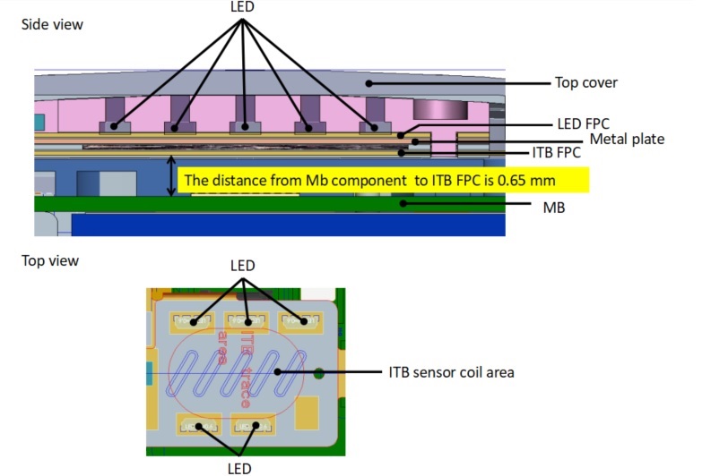
If the LED is placed on the surface of the LED FPC , and the target metal is pasted on the back. ITB FPC is a coil .

1. Does the LED FPC affect the mechanical response of the button?

2.The distance from MB component to ITB FPC is 0.65 mm , and no ferrite sheet between the two , Are there any risks with this design ?

Thank you .

  • Hi Kristin

    Sorry , please refer to the picture below , thanks .

  • Hello User,

    Thanks for your post. Kristin will get back to you shortly. Meanwhile please take a look at the design document on guidance of a mechanical stackup. http://www.ti.com/lit/an/snoa961/snoa961.pdf 

    Thanks. 

  • Hi Victor,

    I suspect that the LED FPC is flexible enough that it will not significantly affect the metal plate, which is much more rigid. However, I am not a mechanical engineer and I strongly recommend that you consult with mechanical engineers on your team to confirm. In general, this mechanical design is quite different from what we've tested, so you may encounter unknown challenges.

    I've answered your second question in this thread: https://e2e.ti.com/support/sensors/f/1023/t/898667

    Best Regards,

  • Hi Kristin :

    Thank you for your feedback , I still have the questions, please help to answer .

    We will choose SUS 430 material

    We use TI's tools , SUS430 can meet the working frequency band , 

    Is this feasible, will there be other problems?

    Or you have better suggestions , thanks .

    Sensor area is 12 mm x 8 mm 

  • Hello,

    Please note that the Excel FEMM tool does not take the target material into account in the LC sensor calculations section. This section uses an ideal aluminum target for all of the target interaction calculations. The section below that shows the outputs of the FEMM simulation does use the specified target material. Unfortunately this is not clearly labeled, and in our next update to the tool we will address this. My apologies for the confusion.

    I recommend using the FEMM calculations to guide the sensor and target design. I expect that the sensor frequency will be lower than the calculations shown in your screenshot (which use the ideal aluminum target). This would decrease the number of skin depths that fit in the target, so you may need to slightly increase the target thickness or increase the sensor frequency. 

    Overall the sensor characteristics look good to me with the aluminum target, and other than the change in skin depth I don't think the FEMM calculations will show any problems with the stainless steel target. As long as the sensor Rp, F, and Q are within the recommended ranges in the datasheet, there shouldn't be any problems with the sensor. I do recommend keeping these values away from the absolute edges of the acceptable ranges. This ensures that small differences between the manufactured sensor and the calculated values will not push the real sensor out of the valid range. 

    Stainless steel is a suitable target and I think the overall stackup looks good. I do want to clarify that there is a cutout in the spacer layer in order to allow the metal to deflect, correct?

    Best Regards,