


Other Parts Discussed in Thread: TDC1000
Hi Team,
The customer is experiencing below issue and needs your help.
The customer used the signal source to output a continuous sine wave signal S1 to simulate the input echo signal received by the receiving probe. When he tested the gain capability of the LNA and PGA in the link CH2 receiving channel of the development board for weak signals, he found that not only did the LNA and PGA not amplify the signal, the signal was attenuated. If the LNA and PGA are bypassed, there is no effect on the amplitude of the signal.
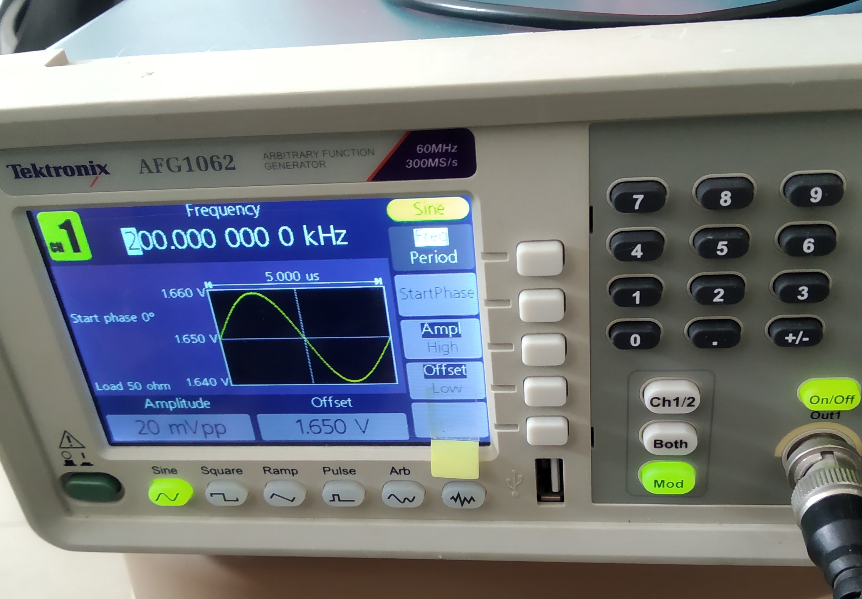
The parameters of S1 are: 20mVPP, 200KHz, offset is 1.65V, as shown in the figure:
Connect this signal to the 11 pin of J5 of the development board. Configure the channel of the GUI of the development board as CH2, use the on-chip clock 8MHZ, and set the frequency division option to frequency division 4 to match the input signal 200K.
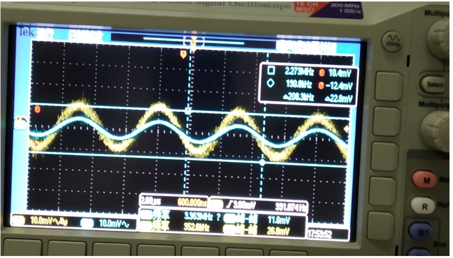
Use the oscilloscope probe to measure the Pin2 of the TDC chip U1 on the development board, that is, the RX2 receiving end. He could see that the peak-to-peak value of the signal after passing through the capacitor C4 is 16mV (blue signal in the figure).

At this time, configure the LNA in the GUI to the Active state, and use an oscilloscope probe to measure R21 near the LNAOUT end.
If he bypassed the LNA in the GUI (bypass option), he will find that the LNAOUT value changes back to 16mV. This means that when the LNA is bypassed, there is no attenuation of the signal. He measured continuously for many times, and this rule remains unchanged. This means that when LNA is enabled, there is no gain to the signal, but instead about 30% attenuation occurs.
He kept the LNA in the Active state, and measured the Pin5 of U1, which is the input of PGAIN, to see that the peak-to-peak value of the signal was 11.4mVpp.

Configure the GNA in the GUI as Active state, set the PGA-GAIN to 21DB gain, and measure R27 near the PGAOUT terminal.

Change the value of PGA-GAIN to 9DB, measure R27 close to the PGAOUT terminal, he could find that the signal peak-to-peak value is 8mVpp,

He continued to adjust the value of PGA-GAIN and found that the larger the value, the stronger the attenuation of the signal. If the PGA is bypassed (bypass option), he will find that the GNAOUT value is 11.2mVpp. This means that the PGA also attenuates the signal, and the degree of attenuation becomes stronger as the PGA-GAIN value increases.
If both LNA and PGA in the GUI are selected as bypass options, he could find that the signal value of R21 close to the LNAOUT terminal and R27 close to the PGAOUT terminal and the corresponding input value amplitude have not been significantly attenuated.
According to the original intention of the customer's development board design, the signal amplitude should be amplified when passing through the LNA and PGA, but why does the LNA and PGA attenuate the signal instead?
Thanks.
Annie

