This thread has been locked.

If you have a related question, please click the "Ask a related question" button in the top right corner. The newly created question will be automatically linked to this question.

DCA1000EVM: FPGA version is not readable from DCA 1000 board

Part Number: DCA1000EVM
Other Parts Discussed in Thread: IWR6843ISK-ODS

Deart TI Support Team,

I am using DCA1000EVM board with IC Boost and mmWave antenna IWR6843ISK-ODS to read raw ADC data from the radar.

I had several issues which I corrected by referring to the guideline provided for similar questions:

1. I programmed FPGA according to the manual and I used the new version 2.8.

2. after preliminary configuration as in the quick manual of DCA1000 EVM, I am running the .lua file to capture the data.

3. I have checked the ethernet cable with wireshark and the data packets are transmitted from the board.

4. I am using the right JTAG connection for programming and FTDI connection for data capturing.

5. I am using two good power supplies, so there is no problem with power supply.

However, the program is unable to read the FPGA version. I receive the following info in the log file. I highlighted the problematic parts in bold.

thank you very much and looking forward to hearing from you soon.

Best Regards,

Saeid

[16:19:26]  [RadarAPI]: Status: Passed
[16:19:26]  Test Source Configuration Success
[16:19:26]  [RadarAPI]: ar1.ProfileConfig(0, 60.25, 100, 6, 60, 0, 0, 0, 0, 0, 0, 29.982, 0, 256, 10000, 0, 131072, 30)
[16:19:27]  [RadarAPI]: Status: Passed
[16:19:27]  ProfileConfig Success
[16:19:27]  [RadarAPI]: ar1.ChirpConfig(0, 0, 0, 0, 0, 0, 0, 1, 1, 0)
[16:19:27]  [RadarAPI]: Status: Passed
[16:19:27]  ChirpConfig Success
[16:19:27]  [RadarAPI]: ar1.EnableTestSource(1)
[16:19:27]  [RadarAPI]: Status: Passed
[16:19:27]  Enabling Test Source Success
[16:19:27]  Test Source Already Enabled...!!!
[16:19:27]  [RadarAPI]: ar1.EnableTestSource(1)
[16:19:27]  [RadarAPI]: Status: Passed
[16:19:27]  [RadarAPI]: ar1.FrameConfig(0, 0, 8, 128, 40, 0, 0, 1)
[16:19:27]  [RadarAPI]: Status: Passed
[16:19:27]  FrameConfig Success
[16:19:27]  [RadarAPI]: ar1.SelectCaptureDevice("DCA1000")
[16:19:27]  [RadarAPI]: Status: Passed
[16:19:27]  SelectCaptureDevice Success
[16:19:27]  [RadarAPI]: ar1.CaptureCardConfig_EthInit("192.168.33.30", "192.168.33.180", "c:22:38:4e:5a:c", 4096, 4098)
[16:19:27]  [RadarAPI]: Sending fpga command to DCA1000
[16:19:37]  [RadarAPI]:
[16:19:37]  FPGA Configuration :
[16:19:37]  Timeout Error! System disconnected
[16:19:37]  [RadarAPI]: Sending fpga_version command to DCA1000
[16:19:47]  [RadarAPI]:
[16:19:47]  
[16:19:47]  Unable to read FPGA Version. [error -5]
[16:19:47]  
[16:19:47]  CaptureCardConfig_EthInit Success
[16:19:47]  [RadarAPI]: ar1.CaptureCardConfig_Mode(1, 2, 1, 2, 3, 0)
[16:19:48]  [RadarAPI]: Sending fpga command to DCA1000
[16:19:58]  [RadarAPI]:
[16:19:58]  FPGA Configuration :
[16:19:58]  Timeout Error! System disconnected
[16:19:58]  CaptureCardConfig_Mode Success
[16:19:58]  [RadarAPI]: ar1.CaptureCardConfig_PacketDelay(25)
[16:19:58]  [RadarAPI]: Sending fpga command to DCA1000
[16:20:08]  [RadarAPI]:
[16:20:08]  FPGA Configuration :
[16:20:08]  Timeout Error! System disconnected
[16:20:08]  [RadarAPI]: Sending record command to DCA1000
[16:20:18]  [RadarAPI]:
[16:20:18]  Configure Record :
[16:20:18]  Timeout Error! System disconnected
[16:20:18]  CaptureCardConfig_PacketDelay failure
[16:20:18]  [RadarAPI]: ar1.CaptureCardConfig_StartRecord("C:\\ti\\mmwave_studio_02_01_01_00\\mmWaveStudio\\Scripts\\..\\PostProc\\adc_data.bin", 1)
[16:20:18]  [RadarAPI]: Sending start_record command to DCA1000
[16:20:18]  [RadarAPI]: Status: Passed
[16:20:19]  [RadarAPI]: ar1.StartFrame()
[16:20:19]  [RadarAPI]: Status: Passed
[16:20:19]  Frame start async event received!
[16:20:20]  Frame End async event received!
[16:20:20]  [RadarAPI]: Frame Ended
[16:20:24]  Please wait for a few seconds for matlab post processing .....!!!!
[16:20:24]  [RadarAPI]: ar1.StartMatlabPostProc("C:\\ti\\mmwave_studio_02_01_01_00\\mmWaveStudio\\Scripts\\..\\PostProc\\adc_data.bin")
[16:20:24]  [RadarAPI]: No of files Captured: 0, Total no of frames for each device : 8
[16:20:24]  Error : The number of files captured is zero!

  • HI, Saeid: 

    From your log, these two lines looks different than ours:

    ar1.CaptureCardConfig_EthInit("192.168.33.30", "192.168.33.180", "c:22:38:4e:5a:c", 4096, 4098)

    ar1.CaptureCardConfig_Mode(1, 2, 1, 2, 3, 0)

    and we have:

    ar1.CaptureCardConfig_EthInit("192.168.33.30", "192.168.33.180", "12:34:56:78:90:12", 4096, 4098)

    ar1.CaptureCardConfig_Mode(1, 0, 1, 2, 3, 30)

    Can you explain why you set the DCA1000 configuration different than default?

    Best,

    Zigang

  • Can you also check the highlighted switch settings with the below figure?

    Best,

    Zigang

  • Dear Zigang,

    I just started working with the board in the past two weeks. And I have followed simply te step-by-step guide provided by TI board manuals. 

    Also, I have used only the software program provided by TI and have not changed any thing.

    May I know how I can change these settings? Should I edit the .lua file? Or is there a place where I can download the original file?

    thank you very much.

    Best Wishes,

    Saeid 

  • Dear Zigang, 

    I saw your attached picture after my previous reply. Sorry for replying twice.

    -- Yes, I have used the switch status on the red board (IC Boost + IWR6843ISK-ODS) as in the picture. 

    -- However, the switch status on the green board (DCA1000 EVM) is different in my case. I just set it according to the manual as follows: 

    I use up and down to show the status of the switch where up and down are according to the picture you have attached.

    SW2.8: USER_SW3 (up) ==> similar to setting in picture.

    SW2.7: USER_SW2 (up)  ==> similar to setting in picture.

    SW2.6: not on USER_SW1 (down) --> since I did not want to force the bit size of the DAC1000 through hardware (according to SW1) and wanted to control it through software. ==> different than the setting in the picture.

    SW2.5: SW_CONFIG (down) --> since I wanted to configure things through software ==> similar to setting in picture.

    SW2.4: RAW_MODE (up) since I wanted to get raw I/Q data from the board for further processing.  ==> similar to setting in picture.

    SW2.3: 1234_MODE (up)  ==> similar to setting in picture.

    SW2.2: ETH_STREAM (down) --> since I wanted to receive data through ethernet cable. ==> different than the setting in the picture.

    SW2.1: LVDS_CAPT (up) ==> similar to setting in picture.

    I hope I have not missed something since these settings are the desired settings in my scenrio and according to the manual.

    thank you very much.

    Best Wishes,

    Saeid

  • Dear Zigang,

    Considering my previous two replies, I also tried to set the switch status SW2 as in the picture you have attached (default model).

    But still I have the same problem and also as you mentioned my log-file is different at those two locations. Please see the log file for the default mode below.

    I also tried to change SW2.2 to ETH_STREAM for ethernet stream but this did not solve the issue either.

    Best Wishes,

    Saeid

    [09:58:38] [RadarAPI]: ar1.CaptureCardConfig_EthInit("192.168.33.30", "192.168.33.180", "c:22:38:4e:5a:c", 4096, 4098)
    [09:58:39] [RadarAPI]: Sending fpga command to DCA1000
    [09:58:49] [RadarAPI]:
    [09:58:49] FPGA Configuration :
    [09:58:49] Timeout Error! System disconnected
    [09:58:49] [RadarAPI]: Sending fpga_version command to DCA1000
    [09:58:59] [RadarAPI]:
    [09:58:59]
    [09:58:59] Unable to read FPGA Version. [error -5]
    [09:58:59]
    [09:58:59] CaptureCardConfig_EthInit Success
    [09:58:59] [RadarAPI]: ar1.CaptureCardConfig_Mode(1, 2, 1, 2, 3, 0)
    [09:58:59] [RadarAPI]: Sending fpga command to DCA1000
    [09:59:09] [RadarAPI]:
    [09:59:09] FPGA Configuration :
    [09:59:09] Timeout Error! System disconnected
    [09:59:09] CaptureCardConfig_Mode Success
    [09:59:09] [RadarAPI]: ar1.CaptureCardConfig_PacketDelay(25)
    [09:59:09] [RadarAPI]: Sending fpga command to DCA1000
    [09:59:19] [RadarAPI]:
    [09:59:19] FPGA Configuration :
    [09:59:19] Timeout Error! System disconnected
    [09:59:19] [RadarAPI]: Sending record command to DCA1000
    [09:59:29] [RadarAPI]:
    [09:59:29] Configure Record :
    [09:59:29] Timeout Error! System disconnected
    [09:59:29] CaptureCardConfig_PacketDelay failure
    [09:59:29] [RadarAPI]: ar1.CaptureCardConfig_StartRecord("C:\\ti\\mmwave_studio_02_01_01_00\\mmWaveStudio\\Scripts\\..\\PostProc\\adc_data.bin", 1)
    [09:59:29] [RadarAPI]: Sending start_record command to DCA1000
    [09:59:29] [RadarAPI]: Status: Passed
    [09:59:31] [RadarAPI]: ar1.StartFrame()
    [09:59:31] [RadarAPI]: Status: Passed
    [09:59:31] Frame start async event received!
    [09:59:31] [RadarAPI]: Frame Ended
    [09:59:31] Frame End async event received!
    [09:59:36] Please wait for a few seconds for matlab post processing .....!!!!
    [09:59:36] [RadarAPI]: ar1.StartMatlabPostProc("C:\\ti\\mmwave_studio_02_01_01_00\\mmWaveStudio\\Scripts\\..\\PostProc\\adc_data.bin")
    [09:59:36] [RadarAPI]: No of files Captured: 0, Total no of frames for each device : 8
    [09:59:36] Error : The number of files captured is zero!
    [09:59:46]
    [09:59:46] ***Script completed successfully.***

  • HI,

    The sw2 configure on DCA1000 board is set to (SW2.5) software config, so you can ignore all other meaning of the switches.  Just set it as mine. 

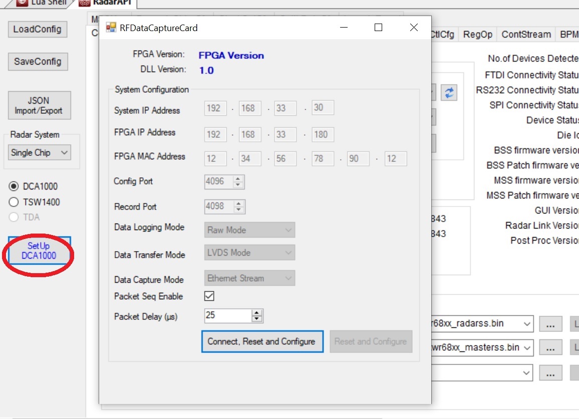
    Inside radar studio, if you click on the "setup DCA1000" on radar studio as below figure, and click on " Connect, reset and config" button.

    you should get these three commands.  

    ar1.CaptureCardConfig_EthInit("192.168.33.30", "192.168.33.180", "12:34:56:78:90:12", 4096, 4098)

    ar1.CaptureCardConfig_Mode(1, 0, 1, 2, 3, 30)

    ar1.CaptureCardConfig_PacketDelay(25)


    Best,

    Zigang

  • Daer Zigang,

    -- ok, then there is no issue with SW2 switch status. Very nice.

    -- I did as you mentioned. I see a window similar to the picture you have attached. Also, I see the following in the log file, which contains the three lines of commands you mentioned. 

    But still I am unable to read the data from the board.

    thanks a lot.

    Best Wishes,

    Saeid

    [17:48:18] [RadarAPI]: ar1.GetCaptureCardDllVersion()
    [17:48:18] [RadarAPI]: Sending dll_version command to DCA1000
    [17:48:18] [RadarAPI]:
    [17:48:18] DLL Version : 1.0
    [17:48:18] [RadarAPI]: ar1.SelectCaptureDevice("DCA1000")
    [17:48:18] [RadarAPI]: Status: Passed
    [17:48:20] [RadarAPI]: ar1.CaptureCardConfig_EthInit("192.168.33.30", "192.168.33.180", "12:34:56:78:90:12", 4096, 4098)
    [17:48:20] [RadarAPI]: ar1.CaptureCardConfig_Mode(1, 0, 1, 2, 3, 30)
    [17:48:20] [RadarAPI]: ar1.CaptureCardConfig_PacketDelay(25)
    [17:48:20] [RadarAPI]: Sending fpga command to DCA1000
    [17:48:20] [RadarAPI]:
    [17:48:20] Invalid lvdsMode value (0). [error -4016]
    [17:48:20] [RadarAPI]: Sending record command to DCA1000
    [17:48:31] [RadarAPI]:
    [17:48:31] Configure Record :
    [17:48:31] Timeout Error! System disconnected
    [17:48:31] [RadarAPI]: ar1.GetCaptureCardFPGAVersion()
    [17:48:31] [RadarAPI]: Sending fpga_version command to DCA1000
    [17:48:41] [RadarAPI]:
    [17:48:41]
    [17:48:41] Unable to read FPGA Version. [error -5]

  • HI, 

    Here is a related e2e thread.  Please go through it carefully

    https://e2e.ti.com/support/sensors/f/1023/t/903342

    Best,

    Zigang

  • Dear Zigang,

    thank you very much for your wonderful help.

    I read the file you mentioned and was able to fix the issue. The problem was due to the firewall blocking the communication through the ethernet cable. Although I checked this with wireshark but it seems firewall was blocking the ethernet any way.

    I have encountered two new issues. And I am not sure if I can close this discussion and open a new one or not. The two issues are as follows:

    1. When I run the .lua file it works very well for the first time and I can see the data visualiyation successfully. However, when I run it again, the software gets stuck while loading the second firmware.

    2. When I receive the raw data from DAC1000 in the file, how can I know which data belongs to which TX-RX pair. I am asking because in IWR6843ISK-ODS I am using there are 3 TX and 4 RX antennas. And, in theory one should be able to extract 3*4=12 data streams corresponding to all TX-RX pairs. 

    -- I would like to know how i can extract these data streams?

    -- I would like to know how TI board works. For example, are all TX antennas transmit simoltensously? Or one after the other in Time Division mode? I would be grateful if you can forward me some document that explains these specifications.

    thank you very much again.

    Best Wishes,

    Saeid

  • Hi, Saeid:

    Glad that your original problem get resolved. 

    For your additional question, I can briefly answer below and you can start a new ticket if you need more help:

    1) The firmware should load only once, and RF init as well.   You can create a new lua script to just do capture part after the initial lua script.  Or manually do the capture part. 

    2) For xWR6843/xwr1642/xwr1843, the binary data format is listed in section 24.8 (DCA1000 EVM capture format (xWR16xx complex, 4 channel, 2 lanes)

    at radar studio users guide located at: C:\ti\mmwave_studio_02_01_01_00\docs\mmwave_studio_user_guide.pdf.

    Both TDM-MIMO and simultaneous TX are supported, you can program through chirp configuration and frame configuration.  (You can find some documentation on section 9 of the above user guide).  In TDM-MIMO, each chirp will enable only one TX and you can program multiple chirps to achieve TDM-MIMO.  In simultaneous TX , each chirp can enable multiple TX and phase rotation can be programmed as well through profile configuration.

    Best,

    Zigang

    Best,

    Zigang  

  • Thank you very much Zigang for your wonderful help and guidance.

    Best Wishes,

    Saeid