This thread has been locked.

If you have a related question, please click the "Ask a related question" button in the top right corner. The newly created question will be automatically linked to this question.

AWR1443BOOST: Realization of SPI control using two AWR1443BOOST

Part Number: AWR1443BOOST
Other Parts Discussed in Thread: AWR1443, MMWAVE-SDK, DCA1000EVM

I had the following exchanges before.
e2e.ti.com/.../906433
-------------------------------------------------------------------------------------------------------------------------------------
2) Is it possible to control two units of AWR1443BOOST with one PC using the first SPI as master and the second module SPI as slave?

Yes the two AWR1443 devices could communicate to each other via SPI. You just need to write your application accordingly.
--------------------------------------------------------------------------------------------------------------------------------------

Would you please tell me the concrete method of creating the application?

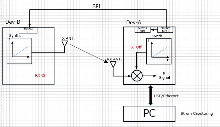
The operation you are trying to perform is to set one AWR1443BOOST to receive only mode and send the send command from the first MCU to the SPI input of the second AWR1443BOOST to see the IQ signal level of the second one. I am thinking.
Probably it is not enough to change the API of the first mmWAVE STUDIO, and I think that it is an image of rewriting SPI related commands with mmWAVE-SDK.

In addition, the execution result of the source edited by mmWAVE-SDK is not displayed by mmWAVE-STIDO, and is it only displayed by mmWave Demo Visualizer?

Thank you.

  • Hello,

    The response [Yes the two AWR1443 devices could communicate to each other via SPI. You just need to write your application accordingly.] was given on old thread was based on this understanding:

    'you need to connect two AWR1443BOOST with each other over SPI where one will act as SPI master whereas another will be SPI slave.'

    Under above understanding, you need to write application on both of AWR1443BOOST to communicate over SPI, you can refer mmWave SDK SPI test application for this.

    Let's name AWR1443BOOST with SPI slave as Dev-A and with SPI Master as Dev-B for simplicity of explaination.

    Now on Dev-A application it needs to listen all the device configuration over SPI from Dev-B.

    On Dev-B, it will send all the command one by one to Dev-A over SPI.

    As final target is to configuration the Rf front end of Dev-A and stream the raw data over LVDS so make it easy to implement you can use CLI command format which Dev-B needs to send over SPI. This CLI command format will be same as used in mmw demo.

    On mmw demo: you need to replace UART interface with SPI for Dev-A application implementation.


    Let me know if I misunderstood or missing anything.

    Regards,

    JG

  • Thank you for your reply.

    First, let's take a closer look at the mmWave SDK SPI test application (mmwave_sdk_user_guide.pdf).
    If there is anything I do not understand, please let me know.

    It is a question together, but in the example of this answer it is streaming raw data via LVDS with Dev-A
    In that case, the Dev-A MCU is like Master, the Dev-A radar module is like Slave1 and the Dev-B radar module is like Slave2.
    Isn't the shape easier?

    If there is a mistake in recognition, I'm sorry.

  • Hello,

    As per picture, you are trying to transmit ONLY from one sensor and receive ONLY from another sensor. And in this case you need to synchronise both of device during frame with capturing data to PC using DCA1000.

    Let me provide an easier solution to realize this setup.

    Frame synchronization allows two (or more) devices to transmit in sync with one another. In order to synchronize, one device is configured as the master, and the other device as slave. The slave device receives the AR_SYNC_IN signal from the master device every time the master device begins the transmission of a frame. (NOTE: here master/slave is not related to cascade setup)

    Perliminaries:

    1. Board modification:

    R165 has to be populated to allow ‘Sync pulse’ to reach the slave device. (R165 is on top of the board near J1). The newest boards would already have it populated.

    The schematic in Figure 2 shows where the resistor R165 is.  

    2. API configuration changes:

    Configure the master as usual.

    When configuring the slave, select hardware triggered mode in the frame-config API. All other APIs will remain unchanged.

    3. Code changes:

    There is no default pin that brings the frame-start signal out of the device. As a consequence, one of the pins need to be re-mapped to provide the frame-start signal. The following code will remap MCUCLKOUT pin to have frame sync signal.

    /* Setup the PINMUX to bring out the FRAME START on PADAY */

    Pinmux_Set_OverrideCtrl(SOC_XWR14XX_PINN9_PADAY, PINMUX_OUTEN_RETAIN_HW_CTRL, PINMUX_INPEN_RETAIN_HW_CTRL);

    Pinmux_Set_FuncSel(SOC_XWR14XX_PINN9_PADAY, 0x7); // FRAME-START TO PAD-AY

    This code can be run in MSS_Init, after the other Pin mux changes.

    Procedure:

    1. Connect the ground between the two boards.
    2. Configure and start the master and the slave.
      1. The slave shouldn't be transmitting now. In order to get the slave to transmit, we need to connect (on the AWR1443BOOST boards), MCUCLKOUT pin (i.e 'pin5 of J5 of master') to SYNC_IN (i.e 'pin9 of J6') on the slave.

    The slave device should start transmitting now.

    Figure 1 MCUCLKOUT from the master

    Figure 2 SYNCIN pin from the slave (Also showing the register R165 that needs to be populated)


    On both of the boards you need to run mmw demo (modified) which includes all the configuration within the application (no UART CLI commands).

    And on Dev-A, you need to stream the raw data over LVDS and capture using DCA1000. Use dca1000 CLI utility to capture the data which is available in mmwave Studio C:\ti\mmwave_studio_02_01_01_00\mmWaveStudio\PostProc\DCA1000EVM_CLI_Control.exe and DCA1000EVM_CLI_Record.exe AND refer DCA1000_Quick_Start_Guide.pdf to use these.

    Regards,

    Jitendra

  • Hello.

    Thank you for your answer.
    I would like to confirm.
    I'll give you additional questions if I don't understand what I tried.

    Best regards,